
A variable friction cable pay-off

A wire pay-off and friction technology, applied in cable laying equipment and other directions, can solve the problems of slow extraction speed, cables falling on the ground next to them, etc., and achieve the effect of simple structure

Active Publication Date: 2016-02-03
FUZHOU UNIV
View PDF4 Cites 0 Cited by
  • Summary
  • Abstract
  • Description
  • Claims
  • Application Information

AI Technical Summary

Problems solved by technology

However, there is a problem in existing cable pay-off devices: when pulling out the cable, the pulling speed is slow at the beginning because the cable roll is heavy and the friction force is relatively large. Lighter, less friction, faster extraction speed, coupled with inertia, it is easy to make extra cables fall on the ground next to it

Method used


Image

  • A variable friction cable pay-off
  • A variable friction cable pay-off
  • A variable friction cable pay-off

Examples


Embodiment 1

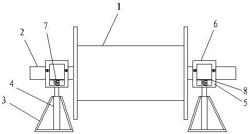
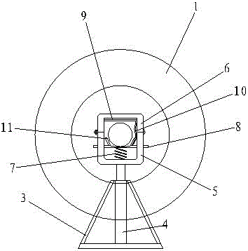
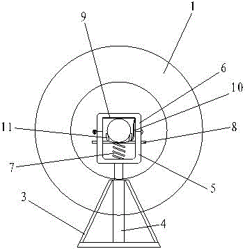
[0019] Embodiment one: if figure 1 As shown, a variable friction cable pay-off device includes two bases 3, a pay-off shaft 2 that rotates synchronously with the cable reel 1, and a brake mechanism. A jack 4 is installed on the base 3, and the jack 4 4 is equipped with a wire release trough, which includes a lower tank body 5 and an upper tank cover 6, a spring 7 is arranged in the lower tank body 5, and a The moving steel plate 8, the two ends of the pay-off shaft 2 are placed on the steel plate 8.

[0020] In this example, if Figure 5 As shown, the brake mechanism includes a brake pad 11 arranged on the steel plate 8 and a brake handle 9 arranged on the inner top of the upper tank cover 6, the brake pad 11 is arranged on both sides of the pay-off shaft 2, and the brake handle 9 The tightness of the brake pads 11 is controlled by the brake line 10 .

[0021] In this example, if Figure 4 As shown, both sides of the spring 7 are provided with protrusions 501 to prevent th...


PUM


Abstract

The invention relates to a variable-friction pay-off unit for a cable. The variable-friction pay-off unit for the cable comprises two substrates, a pay-off shaft and a brake mechanism, wherein the pay-off shaft rotates synchronously with a cable reel; the brake mechanism is used for locking the pay-off shaft; each substrate is provided with a jack; each jack is provided with a pay-off groove; each pay-off groove comprises a lower groove body and an upper groove cover; a spring is arranged in each lower groove body; each spring is provided with a steel plate capable of vertically moving in the corresponding lower groove body; both ends of the pay-off shaft are respectively arranged on the steel plates. The brake mechanism comprises brake blocks and brake handles, wherein the brake blocks are respectively arranged on the steel plates; each brake handle is arranged at the top part of the interior of the corresponding upper groove cover; the brake blocks are respectively arranged at both sides of the pay-off shaft; the brake handle is used for controlling the degree of tightness of the corresponding brake block through a brake cable. The variable-friction pay-off unit for the cable provided by the invention is simple and practical; a brake force can be increased along with the decrease of the weight of a coil of cable; the strength used by wire drawing is kept basically consistent; the pay-off speed is adjusted to prevent the phenomenon that the cable falls on the ground due to the fact that the cable is drawn out excessively.

Description

technical field [0001] The invention relates to a cable pay-off device required for line laying, which is a cable pay-off device with variable friction characteristics. Background technique [0002] When laying lines for communication, power transmission, etc., the cables used are coiled on the cable reel, and the cable needs to be installed on the cable pay-off device to extract the cable. However, there is a problem in existing cable pay-off devices: when pulling out the cable, the pulling speed is slow at the beginning because the cable roll is heavy and the friction force is relatively large. It becomes lighter, the friction force decreases, and the extraction speed becomes faster. In addition, due to the inertia, it is easy to make the extra-extracted cables fall on the ground next to them. The invention can increase the frictional force of the wire release as the weight of the cable roll becomes lighter, and prevent the speed of the wire release from being too fast, s...

Claims


Application Information

Patent Timeline
Patent Type & Authority Patents(China)
IPC IPC(8): H02G1/06
Inventor 黄宴委黄河远熊少华王庭桉
Owner FUZHOU UNIV
Learn More