A low-voltage motor control system

A control system and motor technology, applied in the direction of AC motor control, control system, electrical components, etc., can solve problems such as difficulty in normal heat dissipation, complex secondary circuits, and limited remaining space

Active Publication Date: 2016-02-24
GUANGDONG MINGYANG ELECTRIC CO LTD
View PDF5 Cites 0 Cited by
  • Summary
  • Abstract
  • Description
  • Claims
  • Application Information

AI Technical Summary

Problems solved by technology

[0005] As mentioned above, the control circuit of this type of scheme contains more components, the secondary circuit is more complicated, and the motor circuit is generally installed as a drawer
Due to the relatively fixed positions of the molded case circuit breakers in the drawers of various drawer cabinets (including MNSG cabinets, GCS, GCK and new general-purpose cabinets), the primary input and output terminals are relatively fixed, so the remaining space in the drawer is very limited. There are too many configurations of sub-components, and a slight improper selection of closing and opening relays will cause the components in the drawer to be installed, or all components are barely installed in the drawer, but it is difficult to dissipate heat during normal operation of the equipment, which will affect the life of the components. It is a very big test for safety and use, and it also lays a lot of hidden dangers for future failures.

Method used


Image

  • A low-voltage motor control system
  • A low-voltage motor control system
  • A low-voltage motor control system

Examples


Embodiment Construction

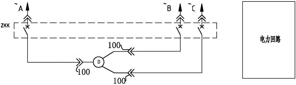
[0024] refer to image 3 , Figure 4 As shown, it is a low-voltage motor control system of the present invention, including a power loop and a ZKK control loop;

[0025] Wherein, the power circuit is composed of a molded case circuit breaker ZKK, a primary plug-in unit 100, and a motor load D sequentially connected from the phase lines A, B, and C of the three-phase AC power supply, see image 3 ;

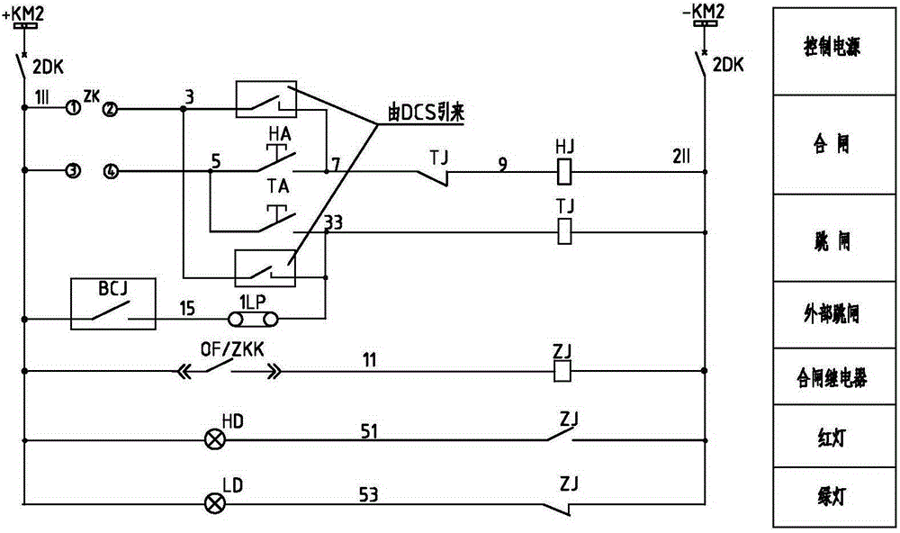
[0026] like Figure 4 As shown, the ZKK control circuit includes a ZKK electric operating mechanism M powered by DC power supply +KM2, -KM2, and at least one combination and opening circuit connected to the ZKK electric operating mechanism M. The ZKK electric operation The mechanism M is used to control the closing and opening of the molded case circuit breaker ZKK. The positive and negative output terminals +KM2 and -KM2 of the DC power supply are provided with a control switch DK. In this example, the control switch DK is a miniature circuit breaker.

[0027] The closing circ...


PUM


Abstract

The invention discloses a low-voltage motor control system, which comprises an electric loop and a ZKK control loop. The electric loop is formed by a moulded case circuit breaker, a plugin and a motor load which are sequentially connected by a phase line A, a phase line B and a phase line C of a three-phase alternating-current power supply. The ZKK control loop comprises a ZKK electric operating mechanism and at least one group of closing circuit and opening circuit, wherein the ZKK electric operating mechanism is powered by a direct-current power supply, the at least one group of closing circuit and opening circuit is connected with the ZKK electric operating mechanism, and the ZKK electric operating mechanism is used for controlling the closing and opening of the moulded case circuit breaker. Compared with an original contactor scheme, the scheme that the moulded case circuit breaker is configured with the electric operating mechanism has the advantage that the required space is much more less; according to the scheme that the moulded case circuit breaker is configured with the electric operating mechanism, the original control requirements can be met, secondary configuration is simplified, space in a drawer is larger, normal heat radiation of equipment during operation is facilitated, and the long-term safe operation of the equipment is favored.

Description

technical field [0001] The invention relates to the field of low-voltage power distribution, in particular to a low-voltage motor control system. Background technique [0002] Most of the 380V low-voltage motors in power plant projects are controlled by contactors. Generally, closing and tripping relays are used to separate the closing circuit and tripping circuit. For the power circuit, see figure 1 , see the attached electrical control circuit diagram for details figure 2 ; The working principle of its control loop: [0003] a. Start: the control circuit miniature circuit breaker DK is energized. If the transfer switch ZK is switched to the local position, the connection between ZK: 3 and ZK: 4 will be connected. Because the control circuit of the tripping relay TJ is in the disconnected state, it will be closed at this time. The TJ closed point in the gate circuit remains unchanged. If the closing button HA is pressed, the closing relay coil is energized, and the HJ op...

Claims


Application Information

Patent Timeline
Patent Type & Authority Patents(China)
IPC IPC(8): H02P25/16
Inventor 田翠芳聂菲菲王秋菊刘永勇谭福光黄天生温建仁于冬初
Owner GUANGDONG MINGYANG ELECTRIC CO LTD
Why Eureka
Try Eureka