Gyromagnetic machine structure

A magnetic machine and box technology, applied in the direction of using variable magnetic field generated by mechanical movement, cleaning method using liquid, heating method, etc. Magnetic therapy health care effect and other issues, to achieve the effect of flat shape, comprehensive action point and long service life

Active Publication Date: 2014-04-30
HEYE HEALTH TECH CO LTD
View PDF9 Cites 3 Cited by
  • Summary
  • Abstract
  • Description
  • Claims
  • Application Information

AI Technical Summary

Problems solved by technology

[0002] In the prior art, various gyromagnetic physiotherapy instruments are of a great variety, such as a roller gyromagnetic machine whose announcement number is CN203043335U's Chinese Utility Model Announcement And notification number is a kind of gyromagnetic machine of Chinese Invention Patent Announcement of CN86206534U, the structure that adopts is relatively simple, all is to drive magnetic object to rotate directly through the rotating shaft of motor, poor structural stability, energy consumption is bigger, produces to human body Stimulation can not achieve a better magnet

Method used


Image

  • Gyromagnetic machine structure
  • Gyromagnetic machine structure
  • Gyromagnetic machine structure

Examples


Example Embodiment

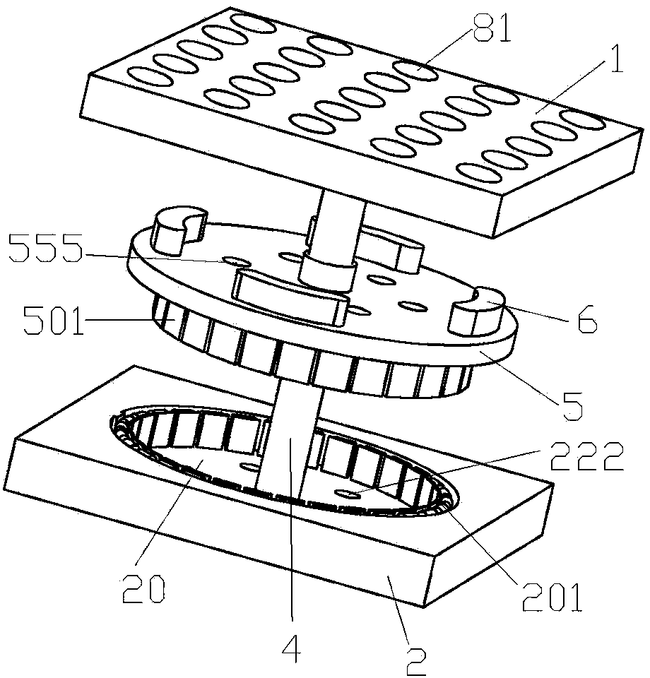
[0040] Example 1, such as figure 1 , 2 , 3, a gyromagnetic machine structure, including an upper box cover 1 and a lower box cover 2, the upper box cover 1 and the lower box cover 2 can be assembled into a closed box, the upper box cover 1 and the lower The opposite side of the box cover 2 is respectively provided with an upper circular inner groove 10 and a lower circular inner groove 20, and an upper positioning groove 110 is opened along the bottom wall of the upper circular inner groove 10 along the lower circular inner groove. The center of the bottom wall of the slot 20 is provided with a lower positioning hole 220 leading to the outside of the box. A main support rod 4 is provided through the lower positioning hole 220 to the upper positioning slot 110. The inner wall of the lower circular inner slot 20 is fixed with a motor stator 201, the main support rod 4 is rotatably connected with a support disc 5, a ring of rotor magnet 501 opposite to the motor stator 201 is fixe...

Example Embodiment

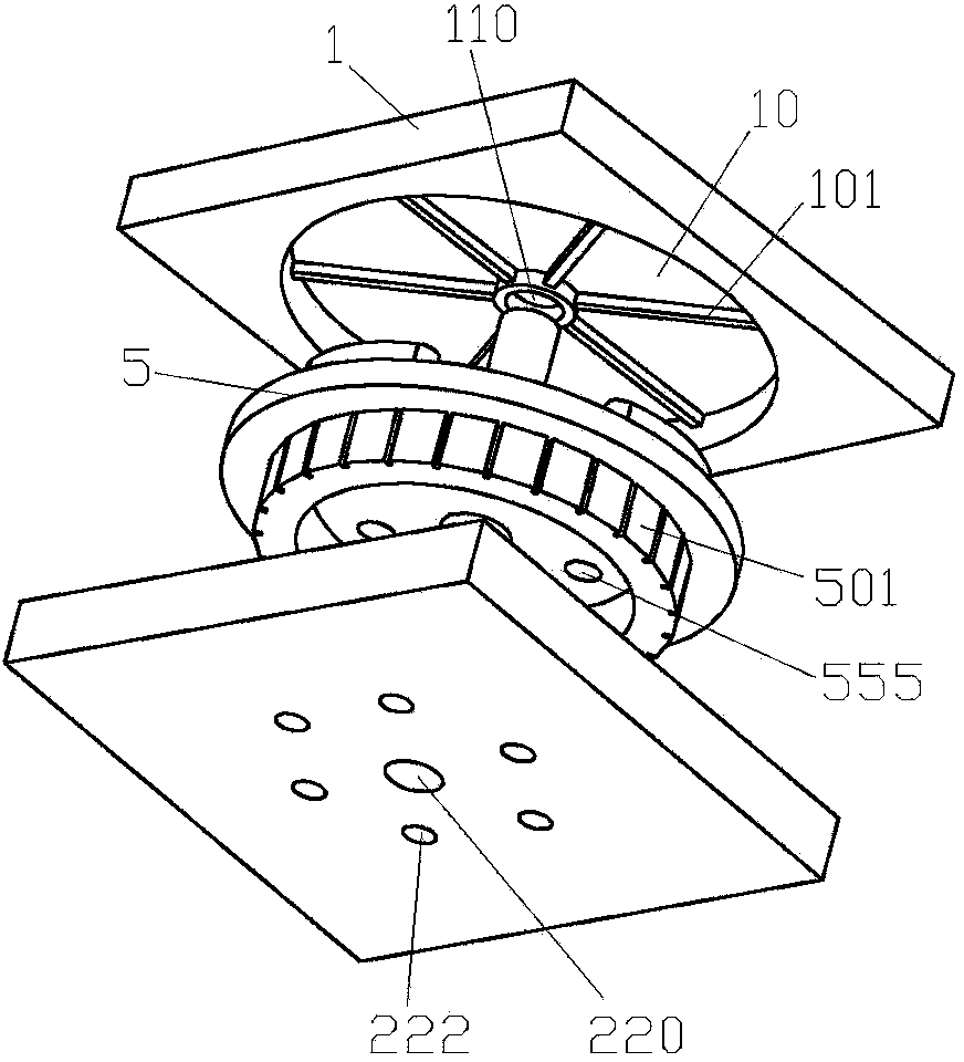
[0041] Example 2, such as Figure 4 , 5 As shown, the difference from Embodiment 1 is that the main support rod 4 is located above the support disc 5 with a carrier plate 7 installed on the carrier plate 7 with a magnetic unit body 6, and the carrier plate 7 can be opened with internal The heat dissipation holes corresponding to the heat dissipation holes 555 can form a better rotating air flow to dissipate heat, and at the same time, the heat conduction and heat radiation efficiency will be higher, and the heat dissipation capacity will be improved.

Example Embodiment

[0042] Example 3, such as Image 6 As shown, the difference from Embodiment 1 is that the strip-shaped heat dissipation partition 101 includes two V-shaped inclined plates 1011 inclined to the bottom wall of the upper circular inner groove 10.


PUM


Abstract

The invention relates to magnet therapy instruments, in particular to a gyromagnetic machine structure. The gyromagnetic machine structure comprises an upper box cover and a lower box cover, wherein the upper box cover and the lower box cover can be spliced to form a closed machine box, an upper circular inner groove and a lower circular inner groove are formed in one side of the upper box cover and the side, opposite to the side of the upper box cover, of the lower box cover respectively, an upper locating groove is formed in the bottom wall of the upper circular inner groove, a lower locating hole is formed in the center of the bottom wall of the lower circular inner groove, and leads to the outside of the machine box, a main supporting rod penetrates through the lower locating hole and is arranged in the upper locating groove, a motor stator is fixed to the inner wall of the lower circular inner groove, a supporting disk is connected with the main supporting rod in a rotary mode, a circle of rotor magnetic steel opposite to the motor stator is fixed to the bottom of the supporting disk, and magnetic units are arranged on the supporting disk. The structure is firm, operation is stable, and the magnet therapy health care effect on a human body is good.

Description

technical field [0001] The invention relates to a magnetic therapy device, in particular to a gyromagnetic machine structure. Background technique [0002] In the prior art, there are many kinds of various gyromagnetic physiotherapy instruments, such as a kind of roller gyromagnetic machine in the Chinese Utility Model Announcement whose announcement number is CN203043335U and a kind of gyromagnetic machine in the Chinese Invention Patent Announcement whose announcement number is CN86206534U. The machine adopts a relatively simple structure, which directly drives the magnetic object to rotate through the rotating shaft of the motor, which has poor structural stability and high energy consumption. The stimulation to the human body cannot achieve a good magnetic therapy health care effect. In addition, when When the rotating magnetic field used for magnetic therapy acts on a certain part of the human body, it cannot completely produce a strong enough magnetic health care effec...

Claims


Application Information

Patent Timeline
IPC IPC(8): A61N2/12F24F6/12B08B3/12
Inventor 李俊方志财胡立江
Owner HEYE HEALTH TECH CO LTD
Why Eureka
Try Eureka