Vertical and horizontal composite core box for simultaneously preparing jacket core and oil duct core

A composite, water-jacketed core technology, applied in casting and molding equipment and other directions, can solve the problems of large space occupied by molds, cannot be directly formed, and a small number of layouts, so as to improve core-making efficiency, save mold costs, and improve tightness. The effect of solidity

Active Publication Date: 2015-07-01
SUZHOU MINGZHI TECH
View PDF6 Cites 0 Cited by
  • Summary
  • Abstract
  • Description
  • Claims
  • Application Information

AI Technical Summary

Problems solved by technology

[0002] Water channels, oil channels, and intake and exhaust channels are important parts of the automobile engine cylinder head (aluminum alloy). Water channels, oil channels, and intake and exhaust channels are part of the inner cavity structure of the engine cylinder head. They cannot be directly formed and need to be designed separately Water jacket core, oil passage core and intake and exhaust passage core are formed. During the casting process of the cylinder head of the automobile engine, the above water jacket core, oil passage core and intake and exhaust passage core are added to the metal mold to form the cavity and form Finally, remove the sand core with a vibrating sand shakeout machine, so that the parts where the sand core was originally placed form the cooling water passage, oil passage, and intake and exhaust passage of the engine. At present, the water jacket core and the oil passage core are generally passed through two sets of molds. , that is, the two equipments are prepared separately, and they are prepared by two sets of molds, which not only increases the number of molds, mold volume, time and labor costs, but also has low core-making efficiency, or integrates two sets of molds into one set of equipment. When two sets of molds are integrated into one set of equipment, in order to facilitate the setting of the ejector mechanism and the sand shooting mechanism, generally the two sets of molds are set to adopt the method of horizontal parting or vertical parting, and both adopt horizontal parting In the method, because the oil channel core is easy to be thin, the sand core is prone to poor compactness, and it uses horizontal sand shooting. Due to the existence of the nozzle and ejector pin, the surface quality of the sand core is poor, and the mold Occupying a large space, when the vertical parting method is adopted, due to the complex structure of the water jacket core mold, the number that can be arranged on each set of equipment is small, resulting in the problem of low core-making efficiency. There is an urgent need for a method that can overcome the above problems at the same time Core box equipment

Method used


Image

  • Vertical and horizontal composite core box for simultaneously preparing jacket core and oil duct core

Examples


Embodiment 1

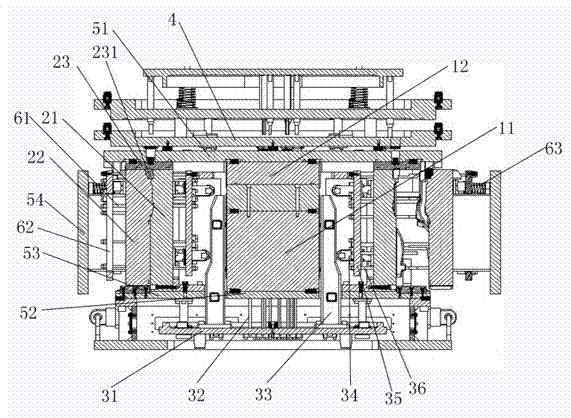
[0016] Embodiment one: see figure 1 , as shown in the legend, a vertical and horizontal composite core box for simultaneously preparing water jacket cores and oil channel cores, including two water jacket core molds, four oil channel core molds, a sand shooting mechanism and A top core mechanism.

[0017] Each of the above-mentioned water jacket core molds comprises a lower core box 11, an upper core box 12 that is arranged on the top of the lower core box 11 and forms a core box cavity with the lower core box 11, and is arranged on the bottom of the lower core box 11 and is connected with the above-mentioned A first core ejector port (not shown in the figure) connected to the cavity of the core box.

[0018] Each of the above-mentioned oil passage core molds includes a static mold 21 arranged on the outside of the lower core box 11 and the upper core box 12, a movable mold 22 arranged on the outside of the static mold 21 and forming a mold cavity with the static mold 21, and...

Embodiment 2

[0030] Embodiment 2: the rest is the same as that of Embodiment 1, the difference is that the outer surface of the above-mentioned first lateral linkage plate is provided with a first slope, and the height of the first slope decreases sequentially from bottom to top, and the above-mentioned The inner surface of the second lateral linkage plate is provided with a second slope, and the height of the second slope increases sequentially from bottom to top.

Embodiment 3

[0031] Embodiment 3: The rest is the same as that of Embodiment 1, except that the outer surface of the first lateral linkage plate is not provided with a first slope, and the inner surface of the second lateral linkage plate is provided with a second slope , the height of the second slope increases sequentially from bottom to top.


PUM


Abstract

The invention discloses a vertical and horizontal composite core box for simultaneously preparing a water jacket core and an oil duct core. The vertical and horizontal composite core box comprises a vertical and horizontal composite a jacket core mold, an oil duct core mold, a sand shooting mechanism and a core ejection mechanism, wherein the water jacket core mold comprises a lower core box, an upper core box which is arranged above the lower core box and forms a core box cavity with the lower core box, and a first core ejection hole which is formed in the bottom of the lower core box and communicated with the core box cavity; the oil duct core mold comprises a static mold arranged on the outer side of the lower core box and / or the upper core box, a movable mold which is arranged on the outer side of the static mold and forms a mold cavity with the static mold, and a second core ejection port which is arranged on the inner side of the static mold and is communicated with the mold cavity. The number of the prepared molds is reduced, the cost of the mold, the production time and labor force are saved, and the core preparation efficiency is greatly improved. Moreover, the surface quality of the oil duct core is improved, and the ramming degree of the oil duct core is improved.

Description

technical field [0001] The invention relates to a core box, in particular to a vertical and horizontal composite core box for simultaneously preparing a water jacket core and an oil channel core. Background technique [0002] Water channels, oil channels, and intake and exhaust channels are important parts of the automobile engine cylinder head (aluminum alloy). Water channels, oil channels, and intake and exhaust channels are part of the inner cavity structure of the engine cylinder head. They cannot be directly formed and need to be designed separately Water jacket core, oil passage core and intake and exhaust passage core are formed. During the casting process of the cylinder head of the automobile engine, the above water jacket core, oil passage core and intake and exhaust passage core are added to the metal mold to form the cavity and form Finally, remove the sand core with a vibrating sand shakeout machine, so that the parts where the sand core was originally placed fo...

Claims


Application Information

Patent Timeline
Patent Type & Authority Patents(China)
IPC IPC(8): B22C7/06
Inventor 陆高春汤晓宁黄佳
Owner SUZHOU MINGZHI TECH
Why Eureka
Try Eureka