Down-hole deep dynamic compactor

A dynamic tamping machine and deep-layer technology, applied in soil protection, construction, infrastructure engineering, etc., can solve the problems of low efficiency, low tamping machine efficiency, inconvenient pile alignment, etc., and achieve simple and reliable operation, improved work efficiency, The effect of improving construction efficiency

Inactive Publication Date: 2014-04-30
SUNWARD INTELLIGENT EQUIP CO LTD
View PDF5 Cites 8 Cited by
  • Summary
  • Abstract
  • Description
  • Claims
  • Application Information

AI Technical Summary

Problems solved by technology

For example, the fixed gantry has no amplitude-changing function, which is inconvenient for pile alignment; the rammer adopts the decoupling and dropping method, which requires a special person to hook, and it is inconvenient to rely on manual hooking alone when the hole is deep
The artificial filling method needs to be transported and introduced into the hole by a special person, and the efficiency is very low
The number of tamping times, the height of the lifting hammer, and the amount of filling in a pile hole of the traditional hole rammer are all controlled manually. Human factors have a great influence, which seriously affects the quality of the pile to a large extent.
[0003] In short, the above-mentioned tamping machine has disadvantages such as low efficiency, poor safety, high construction and maintenance costs, and unguaranteed pile quality, which cannot meet the high-efficiency, low-cost, and high-quality dynamic tamping requirements.

Method used


Image

  • Down-hole deep dynamic compactor
  • Down-hole deep dynamic compactor
  • Down-hole deep dynamic compactor

Examples


Embodiment Construction

[0021] The present invention will be further described below in conjunction with accompanying drawing.

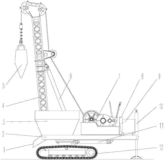
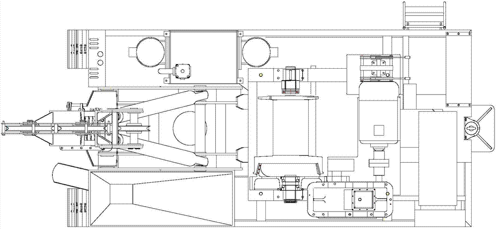
[0022] see figure 1 , figure 2 and image 3 , the chassis 12 is a walking chassis, and the walking chassis is a crawler walking device. The platform 2 is rotatably installed on the chassis 12, and the rotary oil cylinder 11 between the platform and the chassis 12 is arranged on the platform 2. Main pump motor, fuel tank, operating Platform 8, hopper 3 and material tongue 1, hydraulic system and control system 9, the lower end of mast 4 is hinged on platform 2, and two mast oil cylinders 6 are hinged between platform 2 and mast 4, and the wire rope on winch 7 is wound The goose head pulley on the transition pulley and the mast 4 is fixedly connected to the tamper 5, and a leg cylinder 10 is connected to the platform 2; the winch 7 has a retractable oil cylinder or cylinder, and the pipeline and control on the cylinder or cylinder Valve connection; the outlet of the hoppe...


PUM


Abstract

The invention discloses a down-hole deep dynamic compactor. The down-hole deep dynamic compactor comprises a base plate (12), a platform (2), a mast (4), an operation table (8), a hydraulic system, a control system (9), a hoist (7) and a pounder (5), wherein the lower end of the mast (4) is hinged on the platform (2), a mast oil cylinder (6) is arranged between the platform (2) and the mast (4) in hinge mode, a steel wire rope on the hoist (7) is wound around a dynamic hip pulley on the mast (4) and then fixedly connected with the pounder (5), the platform (2) is connected with the base plate (12) through a rotary device, a hopper (3) and a material tongue (1) are arranged on the platform (2), an outlet of the hopper (3) is provided with a hopper door which is butted with the material tongue (1), and the control system (9) is communicated with an operation system of the hoist (7) and an operation system of the hopper door. According to the down-hole deep dynamic compactor, pile butting is facilitated, the pounder of the down-hole deep dynamic compactor does not comprise a hook, and padding quantity of pile holes is convenient to control. Furthermore, the down-hole deep dynamic compactor is simple and reliable to operate, high in pile forming quality, and high in pile forming speed.

Description

technical field [0001] The invention relates to a tamping machine, in particular to an in-hole deep dynamic tamping machine with functions of automatic tamping and automatic blanking into holes. Background technique [0002] At present, if the northwestern part of China is a collapsible loess area, the foundation needs to eliminate the collapsibility of the loess and improve the bearing capacity of the foundation. To eliminate the collapsibility of loess, the bored pile method is adopted, but the bored pile needs to penetrate the collapsible loess layer, and the project cost is too high. At present, the deep dynamic compaction method in the hole is widely used. This construction method is especially suitable for foundation treatment when the deep collapsible loess and high bearing capacity are required, and has the outstanding advantages of low cost and short construction period. At present, there are some problems in the deep dynamic compaction machine in the hole on the m...

Claims


Application Information

Patent Timeline
Patent Type & Authority Applications(China)
IPC IPC(8): E02D3/046E02D3/068
Inventor 朱建新凡知秀司建波姚维熊明强
Owner SUNWARD INTELLIGENT EQUIP CO LTD
Why Eureka
Try Eureka