Method for multi-frequency hybrid calibration of vibration measuring sensor

A sensor and standard sensor technology, applied in instruments, measuring devices, measuring ultrasonic/sonic/infrasonic waves, etc., can solve the problems of frequency domain leakage error excitation bandwidth, complex control technology, damage to the calibrated sensor, etc., to achieve easy control and realization , The control technology is simple, and the effect of avoiding leakage errors

Active Publication Date: 2014-04-30
ZHEJIANG UNIV
View PDF1 Cites 32 Cited by
  • Summary
  • Abstract
  • Description
  • Claims
  • Application Information

AI Technical Summary

Problems solved by technology

However, some frequency components in the spectrum interval of the random signal are easy to coincide with the natural frequency of the fixture and the sensor to be calibrated, thereby exciting resonance and even damaging the sensor to be calibrated. At the same time, the leakage in the frequency domain caused by the time domain truncation of the random signal should also be considered Error and the control of excitation bandwidth and other issues
Compared with fixed-frequency calibration, random calibration has lower precision, complex control technology, and expensive equipment

Method used


Image

  • Method for multi-frequency hybrid calibration of vibration measuring sensor
  • Method for multi-frequency hybrid calibration of vibration measuring sensor

Examples


Embodiment 1

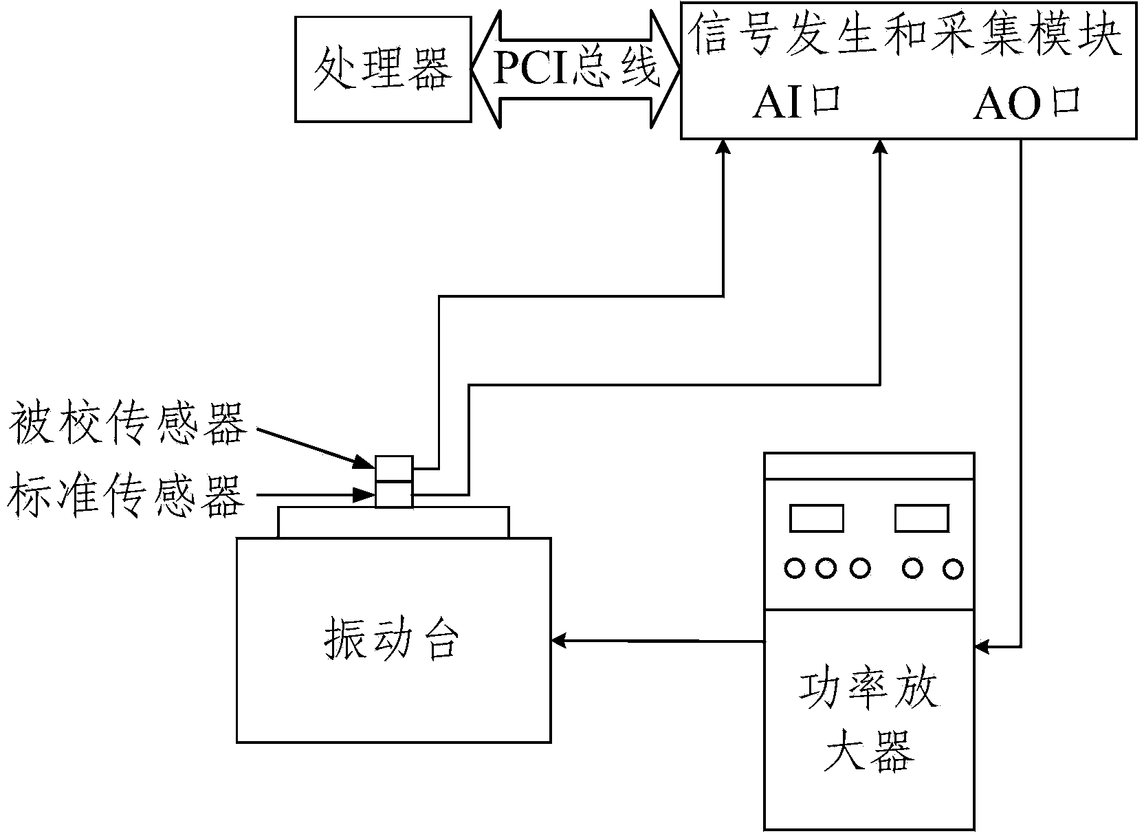
[0024] figure 1 It is a diagram of the hardware structure of the multi-frequency hybrid calibration of the vibration sensor. In this embodiment, both the standard sensor and the sensor to be calibrated are acceleration sensors. The test method includes the following steps:

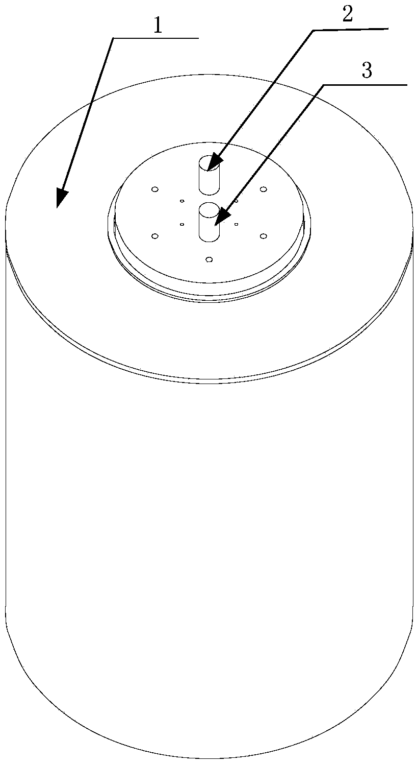
[0025] 1. Select a standard acceleration sensor, refer to figure 2 According to the installation method, the standard acceleration sensor 2 and the acceleration sensor 3 to be calibrated are fixed on the vertical vibration table 1, and the axial direction of the standard acceleration sensor 2 and the acceleration sensor 3 to be calibrated is consistent with the main vibration direction of the vibration table;

[0026] 2. Through the signal generation module, a multi-frequency signal is generated by superimposing a group of sinusoidal signals with different frequencies and random phases. When synthesizing multi-frequency signals, the ratio of each sinusoidal signal frequency is set to be a rational number...

Embodiment 2

[0034] In this embodiment, the standard sensor is an acceleration sensor, and the tested sensor is a speed sensor. In the test method, except that the amplitude spectrum transformation in step 3 is different from that of embodiment 1, the rest of the steps are the same as in embodiment 1. The specific content of step 3 is as follows:

[0035] Collect the output signals of the standard acceleration sensor and the speed sensor to be calibrated, divide the output signal of the standard acceleration sensor by its axial sensitivity and perform FFT transformation to obtain the amplitude spectrum of the acceleration of the shaking table, according to the formula Transform to obtain the amplitude spectrum of the shaking table; perform FFT transformation on the sensor to be calibrated to obtain the amplitude spectrum of the sensor to be calibrated;

[0036] By dividing the amplitude spectrum of the speed sensor to be calibrated by the amplitude spectrum of the shaking table, a set of ...


PUM


Abstract

A method for multi-frequency hybrid calibration of a vibration measuring sensor comprises the following steps that a standard sensor and a measured sensor are fixed on a vibration table, and the axial direction of the two sensors is consistent with the main vibration direction of the vibration table; a signal producing module generates multi-frequency signals; the multi-frequency signals pass through a power amplifier and drive the vibration table; output signals of the standard sensor and the corrected sensor are collected, and the output signal of the standard sensor is converted to obtain an amplitude spectrum of the vibration table; the output signal of the corrected sensor is converted to obtain a corresponding amplitude spectrum; the amplitude spectrum of the vibration table is divided by the amplitude spectrum of the corrected sensor, and the obtained set of quotients is the sensitivity of the corrected sensor at frequency points synthesizing the multi-frequency signals. The method has the advantage of being capable of achieving rapid and accurate calibration of the vibration measuring sensor.

Description

technical field [0001] The invention relates to a method for multi-frequency hybrid calibration of a vibration measuring sensor. technical background [0002] With the rapid development of modern industry, sensors have become an indispensable and important tool in modern industrial testing. As a sensor for measuring vibration, the vibration sensor has been widely used in the field of industrial testing and metrology. Sensor sensitivity is the ratio of the magnitude of the sensor output voltage signal to the magnitude of the mechanical signal input to the sensor. In actual measurement, the measured mechanical vibration signal value input to the sensor can be determined by the output voltage signal value of the sensor and the sensor sensitivity, so the sensor sensitivity is an important indicator to measure the performance of the sensor. Due to the differences in the production process, the sensitivity of each sensor cannot be completely consistent, so the sensitivity of the...

Claims


Application Information

Patent Timeline
Patent Type & Authority Applications(China)
IPC IPC(8): G01H17/00
Inventor 何闻洪起金子迪戴坤鹏
Owner ZHEJIANG UNIV
Why Eureka
Try Eureka