A method of making parallel gratings

A manufacturing method and grating technology, which are applied in diffraction grating, discharge tube/lamp manufacturing, cold cathode manufacturing, etc., can solve the problem of limited exposure wavelength of lithography process and the characteristics and process level of photoresist, limited wavelength and Optical minimum resolution, high price of the whole set of equipment, etc., to achieve the effect of low equipment cost, strong hardness, and improved quality

Active Publication Date: 2016-02-24
安徽皓视光电科技有限公司
View PDF4 Cites 0 Cited by
  • Summary
  • Abstract
  • Description
  • Claims
  • Application Information

AI Technical Summary

Problems solved by technology

[0003] In order to prepare the structural features required by the device, many new processing methods and methods have emerged, such as EDM, photolithography, ultrasonic processing and laser processing, etc., but these processing methods are often limited due to their own working mechanism. For example, the machining accuracy of EDM depends on the accuracy of the machine tool and the thickness of the electrode wire; while the photolithography process is limited by the exposure wavelength and the characteristics and process level of the photoresist. At present, although many researchers are studying deep etching technology, Such as "BOSCH" process technology, but obtaining the micro-nano structure with ideal aspect ratio is still a technical bottleneck in lithography processing; while the object of ultrasonic processing is often hard and brittle materials, and the processing structure error is large, it is difficult to obtain large-area Promotion; when laser processing microstructures, if the laser "thermal effect" is used for cutting, the physical and chemical properties of the cutting edge material will often be changed. Limited by the energy, wavelength and optical minimum resolution of the laser beam

Method used


Image

  • A method of making parallel gratings
  • A method of making parallel gratings
  • A method of making parallel gratings

Examples


Embodiment 1

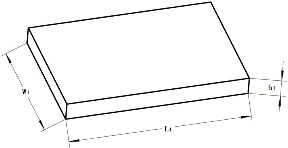
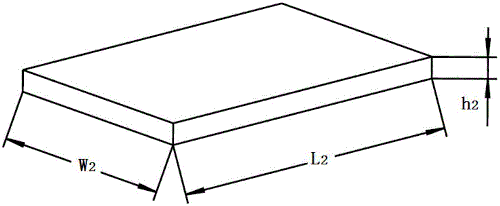
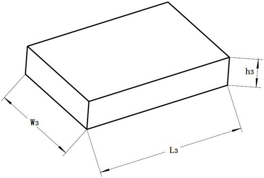
[0084] In this embodiment, a copper-aluminum thin plate is used to manufacture a double-comb-shaped rectangular grating structure in a diffractive radiation device.

[0085] The double-comb grating structure is a slow-wave structure of a diffractive radiation device. The period length of the grating structure is inversely proportional to the frequency of the diffracted radiation. The surface finish also affects the performance of the diffracted radiation. The alignment degree of the gratings of the two rows of gratings It affects the interaction of electromagnetic waves, so it is a key to fabricate a double-comb-shaped grating structure with high precision, smooth sidewalls, and completely aligned grids of two rows of gratings. The following is a brief description of manufacturing a grating by controlling the thickness of different material sheets: a double-comb rectangular grating with a period constant of l=0.13mm, a grating groove depth h=10mm, a groove width d=0.065mm, and ...


PUM


Abstract

The invention discloses a method for manufacturing a parallel grating. The method comprises the steps that the fact that the etching resistance degrees of two different materials to a certain etching solution are different is used, the two materials are manufactured to two kinds of plate bodies respectively through simple mechanical methods such as pressing and grinding, the plate bodies which are made of different materials are arrayed in a crossed mode, and the feature parameters such as the period for manufacturing the grating and the width and the height of the grating are controlled through the dimensions of the two plate bodies; then the plate bodies which are arrayed in the crossed mode are bound to a base plate; at last, a certain solution is chosen to remove the plate body of one material, and the plate body of the other material is reserved to form a grating-shaped structure. The needed equipment is low in cost, the technology is simple, and the manufactured finished parallel grating has the advantages of being high in dimensional precision, good in surface and side face smooth finish, good in uniform consistency, high in hardness, steep in side wall and the like.

Description

technical field [0001] The invention relates to parallel gratings applied to industries such as slow-wave structures of vacuum electronic devices, optics and microelectronics, in particular, the invention relates to a manufacturing method of parallel gratings. Background technique [0002] Parallel grating structures are widely used in slow-wave structures, microwave transmission devices, semiconductor integrated circuits and optical devices in the electric vacuum industry. With the development of science and technology and the improvement of human needs, these devices have higher and higher requirements for parallel gratings. For example, due to the "size co-degree effect", with the increase of the operating frequency of electric vacuum devices, parallel gratings as slow-wave structures are required. The period is getting smaller and smaller, and at the same time, in order to reduce the skin effect and improve the working efficiency of the device, the requirements for the s...

Claims


Application Information

Patent Timeline
Patent Type & Authority Patents(China)
IPC IPC(8): H01J9/00G02B5/18
Inventor 吴华夏席洪柱贺兆昌温旭杰张建成余峰余正红
Owner 安徽皓视光电科技有限公司
Why Eureka
Try Eureka