Welding rack for circuit board welding

A welding frame and circuit board technology, applied in the field of welding frame, can solve the problems of inconvenient welding and poor welding effect, and achieve the effects of good usability, large welding space and good light source

Inactive Publication Date: 2014-04-30
SICHUAN LANXUNBAOER ELECTRONICS TECH
View PDF6 Cites 5 Cited by
  • Summary
  • Abstract
  • Description
  • Claims
  • Application Information

AI Technical Summary

Problems solved by technology

[0003] The invention provides a welding stand for circuit board welding, which solves the problems of poor welding effect and inconvenient welding in previous welding stations

Method used


Image

  • Welding rack for circuit board welding

Examples


Embodiment 1

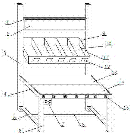
[0015] Such as figure 1 The shown welding frame for circuit board welding includes a square welding platform 4, the lower ends of the four corners of the welding platform 4 are connected with pillars 6, and the pillars 6 of the two corners of the rear end of the welding platform 4 are all upward Brackets 3 are formed by extension, and a storage box 9 and a drawing splint 1 are sequentially arranged between the brackets 3; an LED light source board 13 is arranged on the welding table 4, and a transparent plate is arranged on the upper end of the LED light source board 13, and a transparent board is arranged on the transparent board. Also be provided with an insulating transparent working board 14, the front end of the welding station 4 is also provided with a plurality of power jacks 15; There are a plurality of storage slots 10; the drawing splint 1 is provided with an LED light board 2 inside and the drawing splint 1 is a transparent glass plate.

[0016] The welding station...

Embodiment 2

[0018] In this embodiment, the following structure is added on the basis of Embodiment 1: a switch box 7 is provided at the front end of the welding station 4 .

[0019] In this embodiment, in order to facilitate switching of the LED light source board 13, the LED lamp board 2 and the power jack 15, a switch box 7 is also provided at the front end of the welding station 4, and the switch box 7 can control the circuit switch of the above structure, which is convenient for the staff to use.

Embodiment 3

[0021] This embodiment adds the following structure on the basis of embodiment 1 or embodiment 2: the front end of the storage box 9 is provided with a plurality of identification grooves 12 corresponding to the storage slots 10 .

[0022] In this embodiment, in order to make it easier for the staff to pick and place the corresponding electrical devices, each storage slot 10 is provided with an identification slot 12, and identification pieces for recording information such as the name, model, and service conditions of the electrical device can be pasted in the identification slot 12. Workers will not be confused when picking up the discharge device, avoiding welding errors caused by welders taking wrong electrical parts, and improving welding reliability.


PUM


Abstract

Disclosed in the invention is a welding rack for circuit board welding. The welding rack comprises a square welding platform; pillars are connected to the lower ends of the four corners of the welding platform; and the pillars of the two corners at the rear end of the welding platform extend upwardly to form supports. An object placing box and a drawing clamp plate are successively arranged between the supports from the bottom to top. An LED light source panel is arranged at the welding platform; a transparent plate is arranged at the upper end of the LED light source panel; and an insulated transparent work panel is arranged at the transparent plate. A plurality of power jacks are formed in the front end surface of the welding platform. The two ends of the object placing box are connected to the supports by a rotating shaft; and a plurality of object placing grooves are arranged in the object placing box. An LED lamp panel is arranged inside the drawing clamp plate that is a transparent glass plate. According to the invention, the structure of the welding rack is simple; the light source is good; and the welding space is large. The electric devices and drawings for welding are arranged by a classified way, so that the worker can use the devices and the drawings conveniently. the welding effect and the welding quality are improved; and practicability is high.

Description

technical field [0001] The invention relates to a soldering frame, more specifically to a soldering frame for circuit board soldering. Background technique [0002] When welding electrical components on circuit boards, the electrical components need to be welded accurately and firmly, so it needs to be carried out in an environment with a uniform light source. Mis-welding by personnel, the previous welding station was just a simple platform, equipped with LED desk lamps and other equipment, the entire platform appeared messy, electrical components, drawings, welding equipment, etc. were placed on the platform, welding is extremely inconvenient, and welding The space is small, and the quality and effect of welding are poor. Contents of the invention [0003] The invention provides a welding frame for circuit board welding, which solves the problems of poor welding effect and inconvenient welding of the previous welding stations. [0004] In order to solve the above-mentio...

Claims


Application Information

Patent Timeline
Patent Type & Authority Applications(China)
IPC IPC(8): H05K3/34
Inventor 李胜峰
Owner SICHUAN LANXUNBAOER ELECTRONICS TECH
Why Eureka
Try Eureka