Polishing pad
一种研磨垫、研磨层的技术,应用在研磨垫领域,能够解决耗费时间、切割速率低等问题,达到缩短修整时间、提高制造效率的效果
- Summary
- Abstract
- Description
- Claims
- Application Information
AI Technical Summary
Problems solved by technology
Method used
Image
Examples
Embodiment
[0185] Hereinafter, although an Example is given and this invention is demonstrated, this invention is not limited to these Examples.
[0186] [the first invention]
[0187] [measurement, evaluation method]
[0188] (Measurement of average bubble diameter)
[0189] What was thinly cut out in parallel with a microtome so that the produced polyurethane resin foam may have a thickness of 1 mm or less was used as a sample for the average cell diameter measurement. The sample was fixed on a slide glass, and it observed at 100 times using SEM (S-3500N, Hitachi Scientific Systems Co., Ltd.). Using image analysis software (WinRoof, Mitani Trading Co., Ltd.), the obtained image was measured for all bubble diameters in an arbitrary range, and the average bubble diameter was calculated.
[0190] (Determination of Independent Cell Rate)
[0191] First, the open cell ratio was measured according to the ASTM-2856-94-C method. However, what laminated|stacked 10 circular-punched polyuret...
manufacture example 1
[0210] (synthesis of prepolymer)
[0211] Add 1229 parts by weight of toluene diisocyanate (2,4-body / 2,6-body=80 / 20 mixture), 272 parts by weight of 4,4'-dicyclohexylmethane diisocyanate, 1901 parts by weight Polytetramethylene ether glycol with a molecular weight of 1018 and 198 parts by weight of diethylene glycol were reacted at 70° C. for 4 hours to obtain an isocyanate-terminated prepolymer A (NCO concentration: 2.22 meq / g).
[0212] Similarly, 204 parts by weight of toluene diisocyanate (2,4-body / 2,6-body=80 / 20 mixture), 596 parts by weight of polytetramethylene ether glycol with a number average molecular weight of 1018 are added in the container, The reaction was carried out at 70° C. for 4 hours to obtain an isocyanate-terminated prepolymer B (NCO concentration: 1.48 meq / g).
Embodiment 1
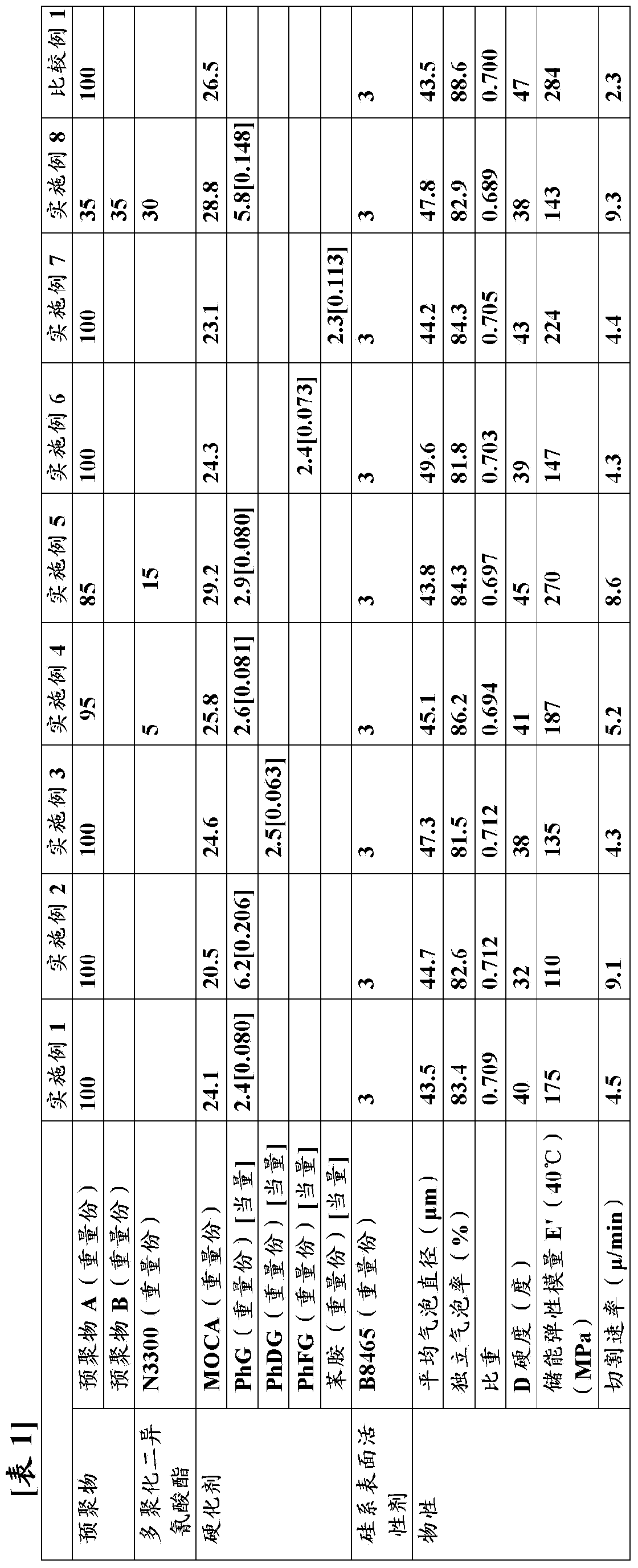
[0214] Add 100 parts by weight of the isocyanate-terminated prepolymer A, 2.4 parts by weight of ethylene glycol monophenyl ether (hydroxyl equivalent to 1 equivalent of isocyanate group: 0.080) and 3 parts by weight of silicon-based surfactant ( Goldschmidt Co., Ltd. make, B8465) was mixed, and it adjusted to 80 degreeC and degassed under reduced pressure. Then, stirring was vigorously performed for about 4 minutes using a stirring blade at a rotation speed of 900 rpm so as to introduce air bubbles into the reaction system. 24.1 parts by weight of 4,4'-methylene bis(o-chloroaniline) (manufactured by Anhara Chemical Co., Ltd., Ihara Curemin MT) previously melted at 120° C. was added thereto. After stirring this liquid mixture for about 1 minute, it poured into the flat-bottomed open mold (cast container). When the fluidity of the liquid mixture disappeared, it was placed in an oven, and post-cured at 110° C. for 6 hours to obtain a polyurethane resin foam block.
[0215] The...
PUM
| Property | Measurement | Unit |
|---|---|---|
| hydroxyl value | aaaaa | aaaaa |
| hydroxyl value | aaaaa | aaaaa |
| hydroxyl value | aaaaa | aaaaa |
Abstract
Description
Claims
Application Information
 - R&D
- Intellectual Property
- Life Sciences
- Materials
- Tech Scout
- Unparalleled Data Quality
- Higher Quality Content
- 60% Fewer Hallucinations
Browse by: Latest US Patents, China's latest patents, Technical Efficacy Thesaurus, Application Domain, Technology Topic, Popular Technical Reports.
© 2025 PatSnap. All rights reserved.Legal|Privacy policy|Modern Slavery Act Transparency Statement|Sitemap|About US| Contact US: help@patsnap.com


