
Switching valve

A technology for switching valves and slide valves, applied to valve details, multi-way valves, valve devices, etc., which can solve problems such as pressure drop in pilot chambers, formation of tiny holes, easily damaged drill bits, etc.

Active Publication Date: 2014-04-30
KYB CORP
View PDF5 Cites 10 Cited by
  • Summary
  • Abstract
  • Description
  • Claims
  • Application Information

AI Technical Summary

Problems solved by technology

[0005] If the cross-sectional area of ​​the small hole is large, the pressure in the pilot chamber will drop
Therefore, the small hole needs to be set to a small cross-sectional area, but it is difficult to form a fine small hole from the outer periphery of the spool to the central axis of the spool.
Especially if the diameter of the slide valve is large, it is easy to damage the drill bit when drilling

Method used


Image

  • Switching valve
  • Switching valve
  • Switching valve

Examples


Embodiment Construction

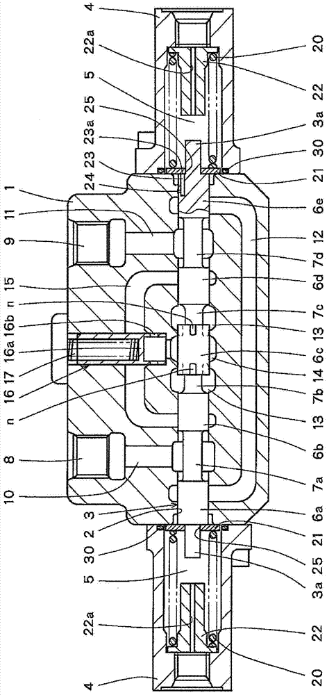
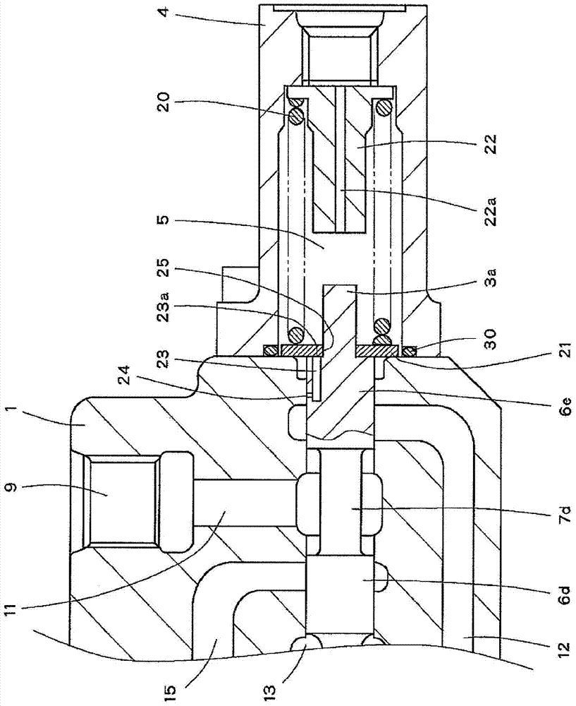
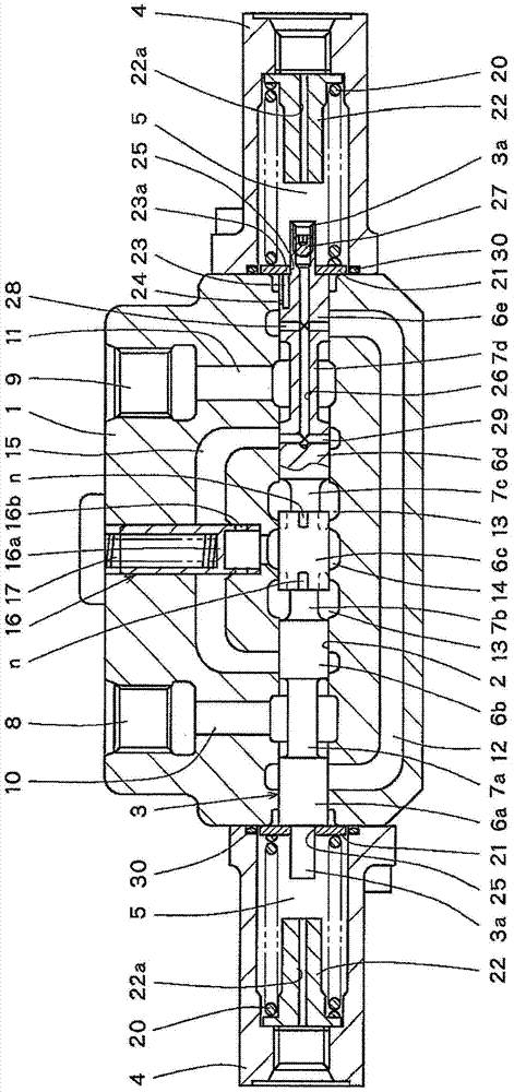
[0015] with reference to the attached figure 1 , The switching valve according to the first embodiment of the present invention includes a spool valve 3 slidably accommodated in a spool valve hole 2 formed in a spool valve housing 1 . The spool valve 3 is formed in a cylindrical shape having a central axis, and both ends of the spool valve 3 respectively face pilot chambers 5 in a pair of covers 4 fixed opposite to the spool valve housing 1 .

[0016] The spool 3 is alternately formed with ring-shaped recessed portions 7 a to 7 d and a plurality of stop ring portions 6 a to 6 e that are in sliding contact with the spool hole 2 . The spool valve 3 slides in the left-right direction in the drawing according to the pilot pressure introduced into the pilot chambers 5 on both sides. Notches n communicating with the annular recessed portion 7b and the annular recessed portion 7c are formed at both ends of the central collar portion 6c.

[0017] A pair of driver port 8 and driver p...


PUM


Abstract

A switching valve is provided with a spool housed in a spool housing, and a pilot chamber facing at least one end of the spool. An axial-direction channel is formed in the spool in the axial direction thereof. The axial-direction channel connects to the pilot chamber, connects to a tank channel according to a change in position of the spool via a small hole opening to the outer circumference of the spool, and discharges air inside the pilot chamber to the tank channel. By forming the axial-direction channel in a position off-centered from the center axis of the spool, the length of the small hole becomes shorter and the machining of the small hole becomes easier.

Description

technical field [0001] The invention relates to a switching valve that switches a flow path by moving a spool valve with pilot pressure. Background technique [0002] JP2003-172310A issued by the Japanese Patent Office proposes a pilot-operated switching valve that uses pilot pressure to move a spool and switches a passage formed in a spool housing to control the flow of pressure oil. [0003] In this switching valve, the end surface of the spool faces the pilot chamber, and the spool is slidably assembled in a spool hole formed in the spool case. [0004] When the pressure is applied to the pilot chamber in the state where the air mixed with the working oil stays in the pilot chamber as air bubbles, the target pilot pressure cannot be accurately applied to the spool due to the contraction of the air bubbles. Therefore, in the prior art, a small hole is provided to discharge the air in the pilot chamber according to the displacement of the spool. [0005] If the cross-sect...

Claims


Application Information

Patent Timeline
Patent Type & Authority Applications(China)
IPC IPC(8): F16K31/122F15B21/04F16K11/07F15B21/044
CPCF15B2211/45F15B2211/329F15B13/042F16K11/07F15B2211/355F16K31/122F15B21/044F16K11/0716Y10T137/86582Y10T137/8671F16K31/1221F16K11/0712F16K31/124
Inventor 寺尾刚
Owner KYB CORP
Learn More