
Light quantity adjustment device and optical apparatus

A technology for adjusting the amount of light and equipment, applied in optics, optical components, apertures, etc., can solve problems such as thinning restrictions, and achieve the effect of reducing size and smoothing shutter operation

Active Publication Date: 2014-04-30
CANON DENSHI KK
View PDF8 Cites 23 Cited by
  • Summary
  • Abstract
  • Description
  • Claims
  • Application Information

AI Technical Summary

Problems solved by technology

Therefore, thinning is limited

Method used


Image

  • Light quantity adjustment device and optical apparatus
  • Light quantity adjustment device and optical apparatus
  • Light quantity adjustment device and optical apparatus

Examples


Embodiment approach 1

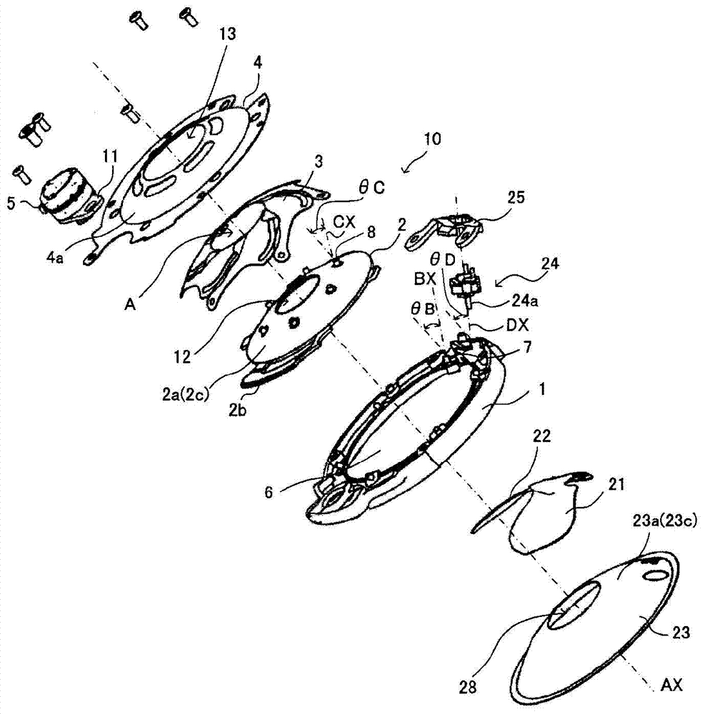
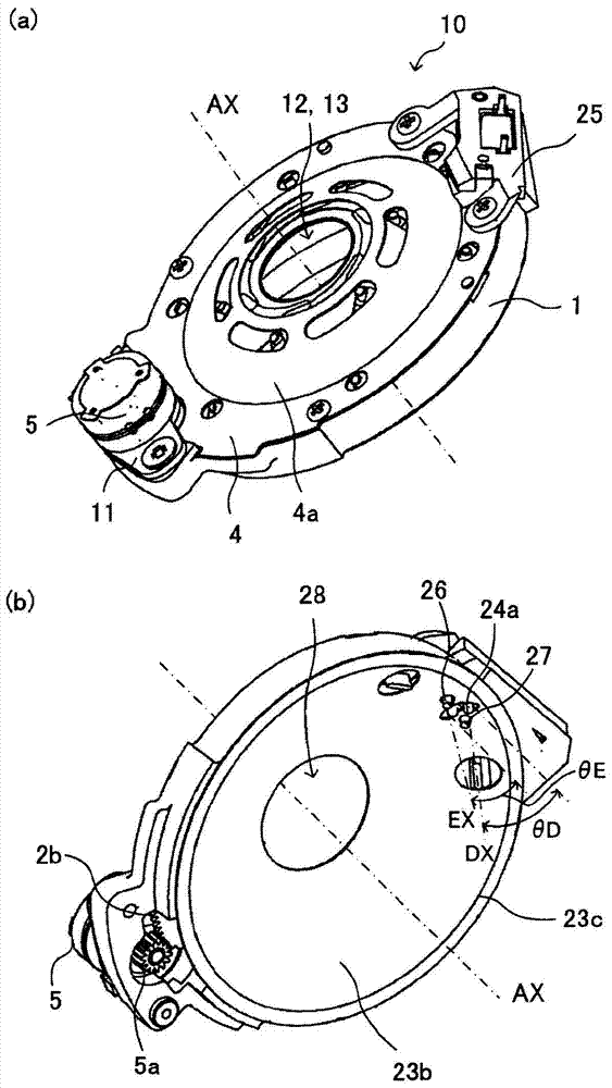
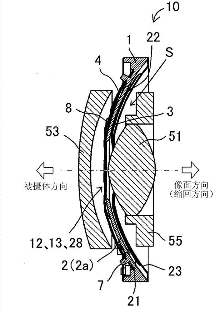
[0044] figure 1 , figure 2 (a) and figure 2 (b) shows the iris-type aperture / shutter device 10 as the light quantity adjustment device according to Embodiment 1 of the present invention. In these figures, a base member 1 formed in a ring shape as a base member is formed with an opening 6 in its inner peripheral portion. In the following description, an axis passing through the center of the aperture / shutter device 10 and orthogonal to the opening faces of the openings 6 formed in the substrate 1 and the opening faces of the fixed openings described below is referred to as "optical axis AX", and The direction in which the optical axis AX extends is referred to as "optical axis direction". In addition, the direction perpendicular to the optical axis direction is called "radial direction".

[0045] A diaphragm blade support protrusion (convex portion) 7 as a diaphragm blade support portion is formed at each of a plurality of circumferential positions of the ring portion of...


PUM


Abstract

[Problem] To suppress increase in size in the radial direction of a light quantity adjustment device having an aperture blade and a shutter blade, and to make same more compact in the optical axis direction. [Solution] A light quantity adjustment device (10) (Fig. 1) has: an aperture blade (3) having an aperture section (3a) for increasing and decreasing the amount of light passing through light passage openings (12, 13, 28), and a supported section (3b); and a shutter blade (21) having a shutter section (21a) for blocking the passage of light in the light passage openings, and a supported section (21b). The supported sections in the aperture blade and the shutter blade each have a slope (a,ss) on the same side in the optical axis direction relative to an opening surface (P), such that the aperture section and the shutter section are separated in the optical axis direction from their respective supported sections. In addition, a drive member (2) has a recessed shape on one side, from the outer peripheral side through to the inner peripheral side. As a result, a recessed space (S) facing the light passage openings is formed further on the inside in the radial direction than the aperture blade, the drive member, and the shutter blade.

Description

technical field [0001] The present invention relates to a light amount adjusting device having at least one of an aperture function and a shutter function. The light amount adjusting device is installed in optical devices such as digital still cameras, video cameras, and interchangeable lenses. Background technique [0002] Optical devices such as cameras are required to be compact. In particular, when the lens barrel for holding the imaging lens protrudes from the camera body in the direction of its optical axis, it is necessary to reduce the length of the lens barrel in the direction of the optical axis to as short as possible. Patent Document 1 discloses a camera having a so-called retractable lens barrel that protrudes from the camera body when the camera is in use (at the time of imaging) and is stored (retracted) when the camera is not in use (at the time of carrying) inside the camera body. In this camera, a lens and a diaphragm serving as a light amount adjusting ...

Claims


Application Information

Patent Timeline
Patent Type & Authority Applications(China)
IPC IPC(8): G03B9/06G02B7/02G02B7/08G03B9/02G03B9/26
CPCG03B9/06G03B9/02G03B9/16G03B9/14G03B11/00G03B2205/00
Inventor 神津聪川久保直树黑泽明柴田光夫
Owner CANON DENSHI KK
Learn More