
Device for producing and method for producing secondary battery

A manufacturing method and a manufacturing device technology, which are applied in the field of storage battery manufacturing and manufacturing devices, can solve problems such as shortening the production interval time, and achieve the effect of shortening the production interval time

Inactive Publication Date: 2014-04-30
ELIIY POWER +1
View PDF4 Cites 5 Cited by
  • Summary
  • Abstract
  • Description
  • Claims
  • Application Information

AI Technical Summary

Problems solved by technology

[0005] For example, in the manufacturing method described in Patent Document 1, a continuous separator is sandwiched between a pair of rollers, and the separator is bent in a zigzag shape by reciprocating the pair of rollers in the horizontal direction. Every time the roller reciprocates, the positive and negative plates are alternately placed on the separator, so it is difficult to greatly shorten the production interval time

Method used


Image

  • Device for producing and method for producing secondary battery
  • Device for producing and method for producing secondary battery
  • Device for producing and method for producing secondary battery

Examples


Embodiment approach 1

[0039] Such as figure 1 as well as figure 2As shown, a prismatic battery (battery) 1 as a lithium ion storage battery includes a prismatic case 2 , and an electrode plate group 3 is housed in the prismatic case 2 . A positive terminal and a negative terminal (not shown) are provided at predetermined positions of the rectangular case 2 . Furthermore, an electrolytic solution obtained by mixing a lithium salt with an organic solvent is filled in the rectangular case 2 .

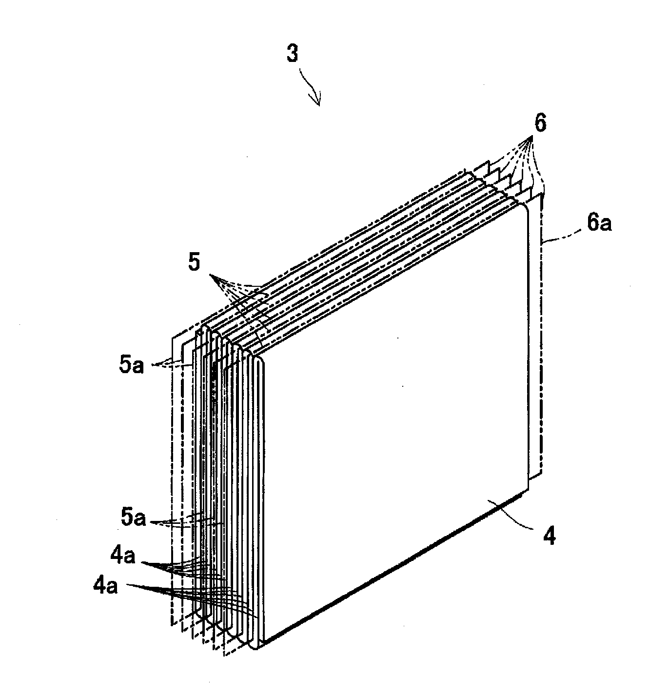
[0040] The electrode plate group 3 includes a separator 4 that is bent in a zigzag shape, and positive electrode plates 5 and negative electrode plates 6 that are alternately inserted into the valley grooves 4 a of the separator 4 . The positive electrode plates 5 and the negative electrode plates 6 are stacked alternately with the separators 4 interposed therebetween, and the separators 4 are stacked flat. The positive electrode plate 5 and the negative electrode plate 6 have lead portions 5a, 6a protrudi...

Embodiment approach 2

[0071] Figure 13 It is a schematic diagram showing the manufacturing apparatus of the electrode plate group concerning Embodiment 2. In addition, the same code|symbol is attached|subjected to the same member, and overlapping description is abbreviate|omitted.

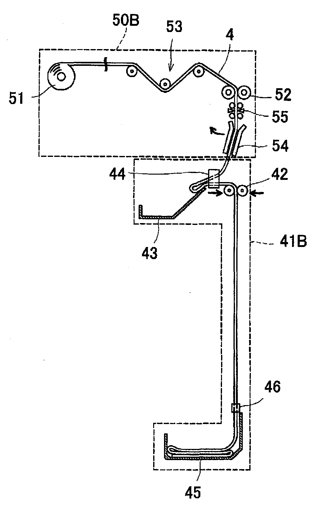
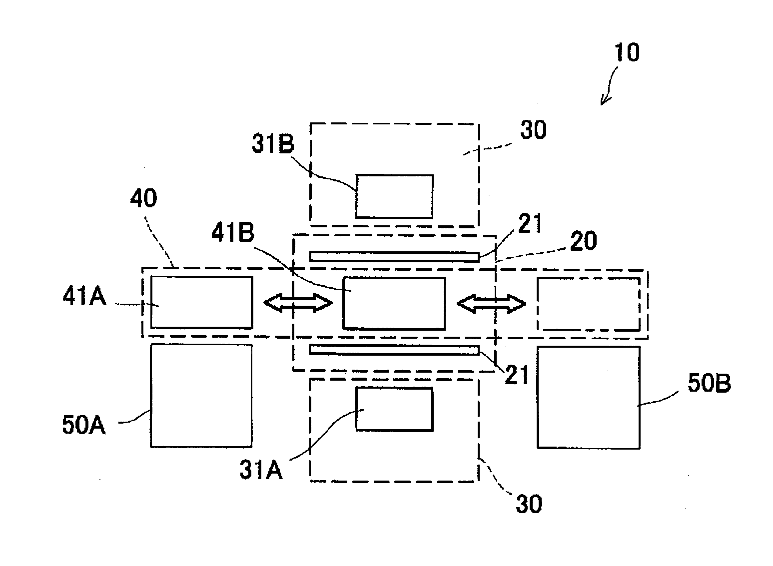
[0072] The manufacturing apparatus 10A according to this embodiment is such as Figure 13 As shown, one supply mechanism 50 is provided for one zigzag bending mechanism 20 , and the conveyance mechanism 40A is also provided with one holding and conveying member 41 corresponding to the one supply mechanism 50 . The structure holding the transport member 41 is the same as that of the first embodiment, but differs from the first embodiment in that it is fixed at a position facing the zigzag bending mechanism 20 and does not move.

[0073] In this manufacturing apparatus 10A, the separators 4 are supplied and held by the holding and conveying means 41 in the same procedure as in the first embodiment (see Figure 7 ~Figu...

Embodiment approach 3

[0077] Figure 14 is a schematic diagram showing an electrode group according to Embodiment 3, Figure 15 It is a schematic diagram showing the manufacturing apparatus according to Embodiment 3. In addition, the same code|symbol is attached|subjected to the same member, and overlapping description is abbreviate|omitted.

[0078] Such as Figure 14 As shown, the electrode plate group 3A according to Embodiment 3 is a stacked body including a continuous stacked body 100 bent in a zigzag shape and a positive electrode plate 5 inserted into each tooth valley groove 100 a of the stacked body 100 . constituted. The laminated body 100 is a laminated body in which the negative electrode plate 6A is sandwiched between two separators 4A. Therefore, the positive electrode plate 5 inserted into each valley groove 100a of the stacked body 100 faces the negative electrode plate 6A via the separator 4A.

[0079] In addition, even in such a structure of the present embodiment, as in the ...


PUM


Abstract

The present invention pertains to a device for producing and a method for producing a secondary battery. Secondary batteries are produced by interposing a separator between positive and negative electrode plates, but conventionally, the separators are sandwiched by a pair of rollers, the rollers are caused to reciprocate in the horizontal direction, the separator is folded in a zig-zag fashion, and the positive and negative electrode plates are alternatingly placed on the separator each time the pair of rollers reciprocate, and so there has been the problem that it has been difficult to greatly reduce takt time. The present invention resolves the problem for example by method having: a step for pressing a separator (4) by means of a plurality of guide members (21), folding the separator in a zig-zag fashion; a step for forming a layered body having alternatingly overlapping positive electrode plates and negative electrode plates by alternatingly inserting a positive electrode plate (5) and negative electrode plate (6) in each furrow of the zig-zag folded separator with the separator therebetween; a step for removing the guide members from within each furrow of the separator; and a step for pressing the layered body in the direction of layering; the step for folding in a zig-zag fashion being performed after causing the separator to be in a tension-free state.

Description

technical field [0001] The present invention relates to a method and apparatus for manufacturing a storage battery used in vehicles, electrical equipment, and the like. Background technique [0002] A storage battery such as a lithium ion storage battery has an electrode plate group formed by alternately overlapping positive electrode plates and negative electrode plates with a separator interposed between positive and negative electrode plates. As one of the manufacturing devices of the electrode plate group, there is a manufacturing device that bends the continuous body of the separator in a zigzag shape, inserts the positive electrode plate and the negative electrode plate into each tooth valley, and presses them into a flat zigzag stacking method. (For example, refer to Patent Document 1). [0003] Patent Document 1: Japanese Patent Application Laid-Open No. 2004-22449. [0004] In such a zig-zag stacking manufacturing device, for example, a stacking method in which sh...

Claims


Application Information

Patent Timeline
Patent Type & Authority Applications(China)
IPC IPC(8): H01M10/04H01M10/0583
CPCH01M10/052H01M10/0404H01M10/0583H01M10/0459H01M10/045Y02E60/10Y10T29/49108Y10T29/53135Y02P70/50H01M6/005H01M6/02H01M10/0525H01M2220/20H01M2220/30Y02T10/70
Inventor 佐藤寻史山浦诚司坂田卓也
Owner ELIIY POWER
Learn More