Bidirectional anti-explosion floor drain

A floor drain and body technology, applied in waterway systems, drainage structures, water supply devices, etc., can solve the problems of increasing the thickness of the structural bottom plate, small drainage, water loss of the floor drain water seal, etc., to achieve the reduction of its own volume, increase of drainage, and drainage powerful effect

Inactive Publication Date: 2014-05-07
杜青
View PDF5 Cites 3 Cited by
  • Summary
  • Abstract
  • Description
  • Claims
  • Application Information

AI Technical Summary

Problems solved by technology

[0005] 1. Only one-way explosion-proof: Due to the lack of effective fixing measures for the bell jar of the explosion-proof floor drain, when the shock wave rushes from the bottom of the floor drain to the direction of the mouth, especially when the direction of the nuclear explosion shock wave changes alternately (such as positive and negative pressure alternately appear ), its reverse explosion-proof function is unreliable;
[0006] 2. Small displacement: The bell-type explosion-proof floor drain reduces the cross-section of the drainage in order to maintain the water seal. If the displacement needs to be increased, the size of the explosion-proof floor drain must be increased, because the floor drain must be placed in the structural layer, thus It may increase the thickness of the structural bottom plate and greatly increase the project cost;
[0007] 3. Airtightness is unreliable: the airtightness of the shock wave is realized by pressing the rubber gasket on the upper edge of the lower opening of the drain body through the inner surface of the bell jar of the drain cover.
The ductility of the rubber gasket is poor. When the processing of the upper edge of the lower opening of the leak body is slightly irregular or the end surface is slightly out of parallel with the inner surface of the bell jar of the drain cover, it will lead to poor airtightness, thereby destroying the entire protection project. airtightness;
[0008] 4. Flue gas anti-channeling: When the explosion-proof floor drain installed in the multi-storey underground project is used to discharge the fire-fighting wastewater from the upper layer to the next layer, due to the lack of water replenishment, the water seal of the floor drain is often in a state of dehydration, resulting in water seal fail
In the event of a fire, there is a danger of fire smoke spreading between the upper and lower floors through the existing explosion-proof floor drain

Method used


Image

  • Bidirectional anti-explosion floor drain
  • Bidirectional anti-explosion floor drain
  • Bidirectional anti-explosion floor drain

Examples


Embodiment Construction

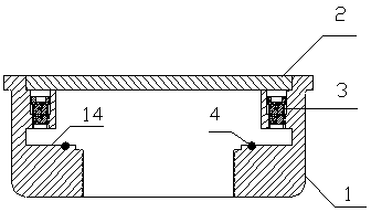
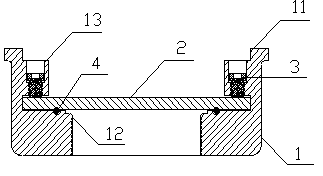
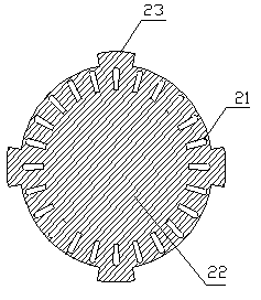
[0029] Such as figure 1 As shown, the two-way explosion-proof floor drain of the present invention includes a body 1 and a grate 2. The body 1 has an upper port 11 as a water inlet and a lower port 12 as a water outlet. There is a water hole 21 on the grate 2. The body The inner side of the upper opening 11 is provided with a plurality of radial recesses 13 (i.e., the inner side of the upper opening of the leak body in the prior art), and the outer edge of the grate 2 is provided with a plurality of radial protrusions 23 (i.e., the inner side of the upper opening of the prior art). The upper edge of the middle drain cover is radially convex corresponding to the block), and the body 1 is provided with a locking device 3 that positions the protruding portion 23 on the grate 2 below the concave portion 13 on the body 1 to seal the floor drain.

[0030] The locking device 3 is a bolt that is screwed into the recessed portion 13 .

[0031] Such as figure 1 As shown, in normal use...


PUM


Abstract

The invention discloses a bidirectional anti-explosion floor drain, comprising a main body with an upper opening and a lower opening, and a grate with water holes, wherein the inner side of the upper opening of the main body is provided with a plurality of radial concave parts, the outer edge of the grate is provided with a plurality of radial convex parts, and the main body is provided with a locking device for positioning the convex parts on the grate into the concave parts on the main body and then sealing the floor drain. The bidirectional anti-explosion floor drain provided by the invention is simple in structure and reliable in seal, and can prevent being penetrated by shock wave from any direction.

Description

technical field [0001] The invention belongs to the technical field of drainage floor drains, in particular to a bidirectional explosion-proof floor drain with explosion-proof functions in both positive and negative directions. Background technique [0002] The floor drain selected in the part of the protection project that may be affected by the shock wave should be an explosion-proof floor drain, so the explosion-proof floor drain is widely used in the drainage of ground water in various protection projects. [0003] The existing explosion-proof floor drain adopts a bell-type structure, such as the Chinese utility model patent "Explosion-proof floor drain" (patent number: ZL95238691.7, announcement date: 1997.11.12), including a drain body with an upper port and a lower port. There is a rib that extends into it and connects with the lower mouth, and also includes a drain cover with a water hole on the upper part and a nearly hemispherical bell jar on the lower part. The dr...

Claims


Application Information

Patent Timeline
Patent Type & Authority Applications(China)
IPC IPC(8): E03F5/04E03F5/06
Inventor 杜青丁志斌
Owner 杜青
Why Eureka
Try Eureka