
Combined type high-rise structure energy dissipation and shock absorption enhancement layer

A high-rise structure and combined technology, applied in the direction of earthquake resistance, building components, etc., can solve the problems of structural damage mechanisms that are difficult to present ductile yielding, collapse, and sudden changes in internal forces

Active Publication Date: 2014-05-07
TONGJI UNIV
View PDF6 Cites 12 Cited by
  • Summary
  • Abstract
  • Description
  • Claims
  • Application Information

AI Technical Summary

Problems solved by technology

Under wind loads, setting a reinforced floor is an effective method to reduce the horizontal displacement of the structure; however, under earthquake action, the setting of the reinforced floor will cause a sudden change in the structural stiffness and internal force at the reinforced floor and its nearby floors, changing the overall transmission of the structure. The stress path makes the damage of the structure easier to concentrate on the reinforced layer and its nearby floors. Due to the stress concentration, a weak layer is formed, which leads to the damage or even collapse of the structure. The damage mechanism of the structure is difficult to show the ductile yield mechanism.

Method used


Image

  • Combined type high-rise structure energy dissipation and shock absorption enhancement layer
  • Combined type high-rise structure energy dissipation and shock absorption enhancement layer
  • Combined type high-rise structure energy dissipation and shock absorption enhancement layer

Examples


Embodiment Construction

[0016] The present invention will be further described below in conjunction with the embodiments shown in the accompanying drawings.

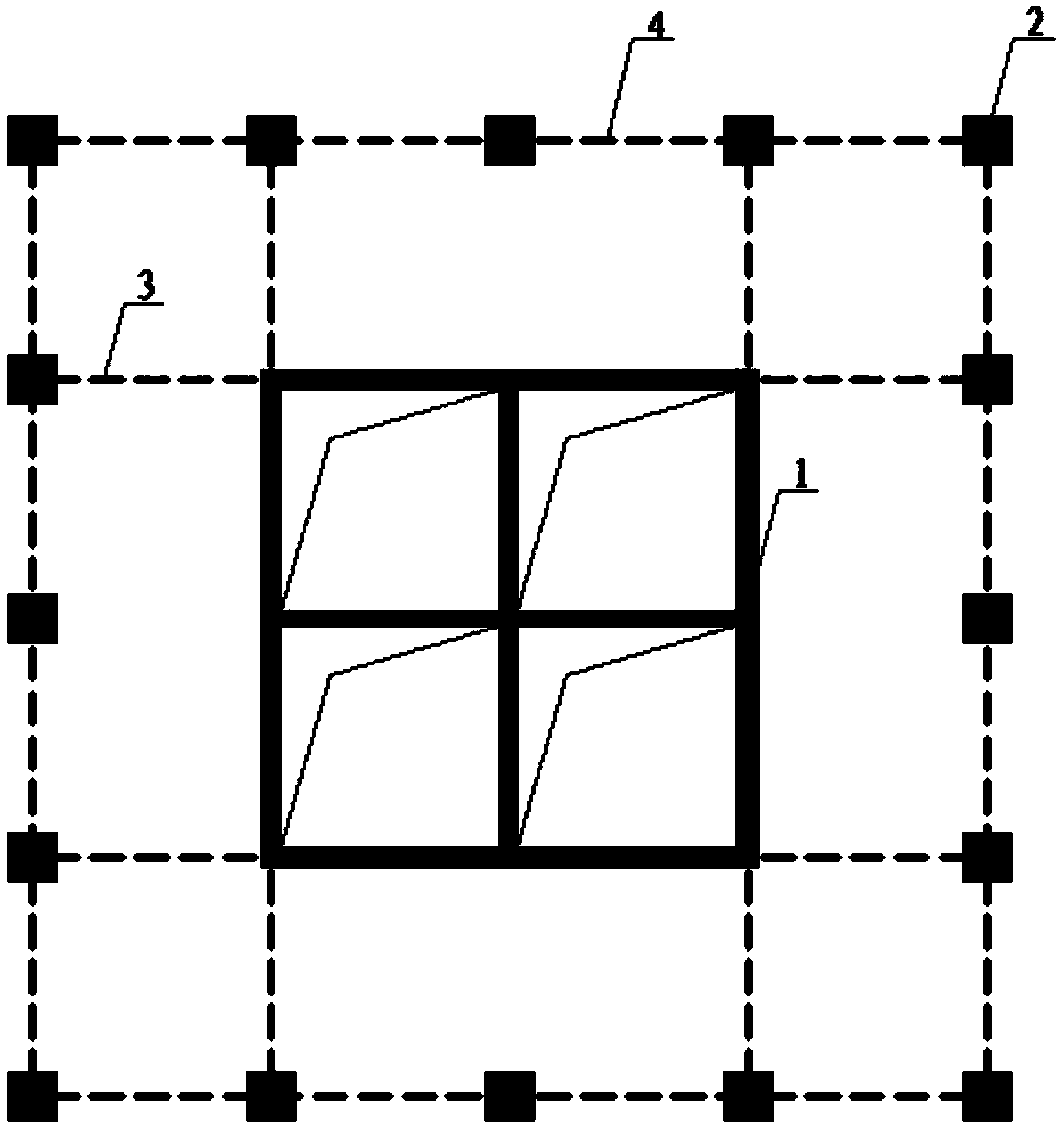
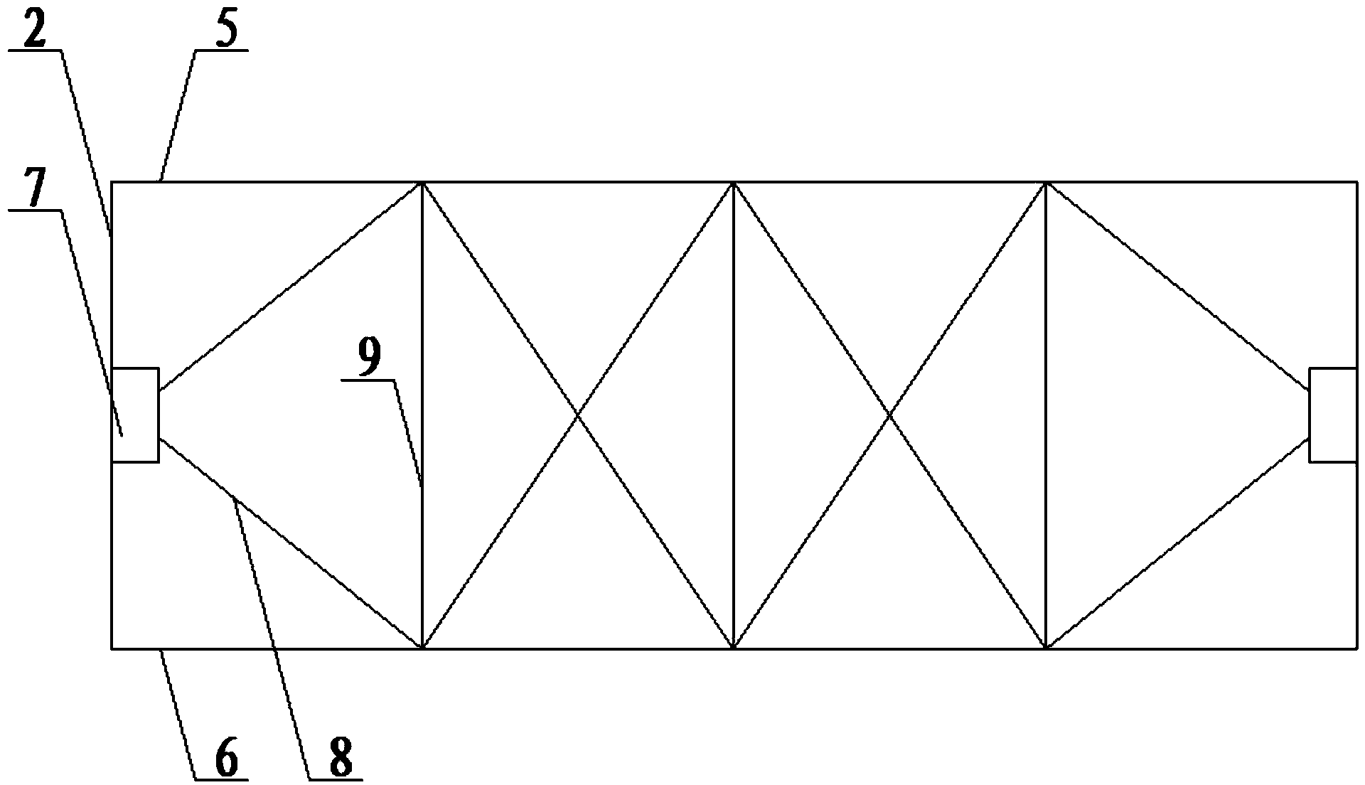
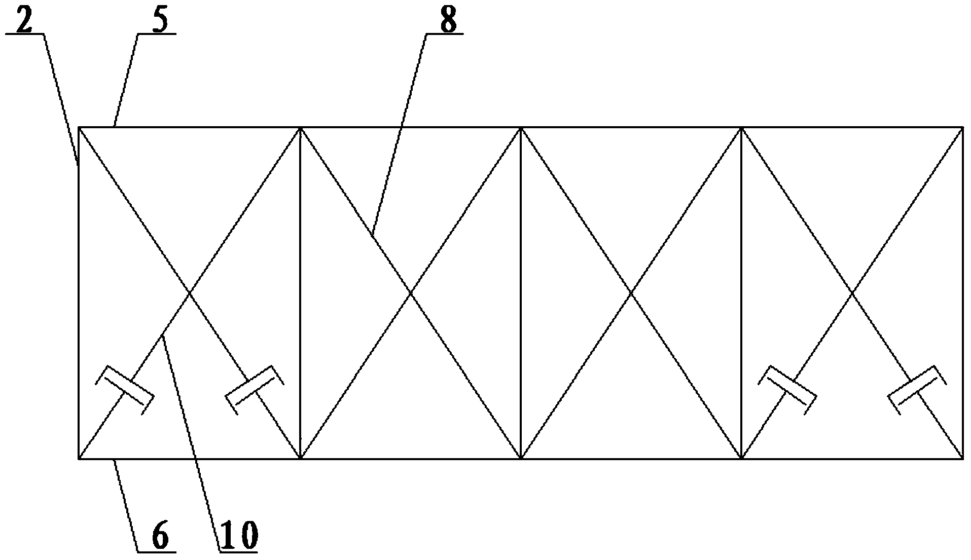
[0017] Such as figure 1 As shown, a combined high-rise structure energy dissipation and shock absorption strengthening layer, its purpose is to improve the overall lateral stiffness of the structure, to achieve the structure's wind resistance and seismic performance goals, composed of energy dissipation and shock absorption outrigger 3 and energy dissipation The shock-absorbing ring belt truss 4 is composed of the original structural system, including the core tube 1 set in the middle of the building and the frame column 2 set on the periphery of the building. The energy-dissipating and shock-absorbing outrigger 3 is connected between the core tube 1 and the frame column 2. The energy-dissipating and shock-absorbing outrigger truss 3 is perpendicular to the frame column 2, and a plurality of energy-dissipating and shock-absorbing outrigger trus...


PUM


Abstract

The invention discloses a combined type high-rise structure energy dissipation and shock absorption enhancement layer. The combined type high-rise structure energy dissipation and shock absorption enhancement layer comprises a core tube positioned in the middle of a building and frame columns on the periphery of the building, wherein an energy dissipation and shock absorption outrigger truss is connected between the middle core tube and each peripheral frame column; an energy dissipation and shock absorption band truss is connected between the peripheral frame columns. The energy dissipation and shock absorption outrigger trusses can improve the integral structural lateral stiffness, thus providing the additional structural damping and reducing the structural horizontal lateral displacement; the energy dissipation and shock absorption band trusses can strengthen the interaction among the peripheral frame columns, thus coordinating the deformation of the frame columns, reducing the deformation difference, strengthening the structural integrality and enabling the structural stress to be uniform. The side span of each energy dissipation and shock absorption outrigger truss is internally provided with a metal yielding type damper, and the side span of each energy dissipation and shock absorption band truss is internally provided with a viscous damper. Under the load effect of wind and the effect of frequent seismic intensity earthquakes, main structural energy dissipation components are viscous dampers; under the effect of design intensity and frequent seismic intensity earthquakes, main structural energy dissipation components are metal yielding type dampers.

Description

technical field [0001] The invention belongs to the field of civil structure engineering, and relates to an energy dissipation and shock absorption structure, in particular to an energy dissipation and shock absorption structure of a high-rise structure. Background technique [0002] In the past 100 years, the design and construction technology of high-rise buildings has achieved rapid development. With the development of the economy, a large number of super high-rise building structures have been built, which has become the main trend of rapid urban construction and development. Many of the super high-rise buildings adopt the structural form of a combination of the middle core tube and the peripheral frame, and coordinate the core by setting a structural reinforcement layer. The force and deformation of the tube and the frame constitute an efficient lateral force-resistant structural system. The reinforced floor is usually arranged on the technical floor (equipment floor, ...

Claims


Application Information

Patent Timeline
IPC IPC(8): E04B1/98
Inventor 蒋欢军祝玉龙
Owner TONGJI UNIV
Learn More