A three-dimensional swirling magnetic gap magnetorheological valve structure

A magnetorheological valve and magnetic gap technology, applied in the field of hydraulic control valves, can solve the problems of insufficient use of the coil magnetic field, increase the difficulty of assembly of the magnetorheological valve, the failure rate, and increase the valve volume, etc., so as to improve the flow channel. Effects of length, size reduction, lengthening path length

Inactive Publication Date: 2015-09-02
HEILONGJIANG UNIVERSITY OF SCIENCE AND TECHNOLOGY
View PDF6 Cites 0 Cited by
  • Summary
  • Abstract
  • Description
  • Claims
  • Application Information

AI Technical Summary

Problems solved by technology

Although such a structure can be set in two or more groups to meet the pressure and flow requirements, such a structure does not make full use of the coil magnetic field, and will increase the volume of the valve, increasing the difficulty of assembling the magneto-rheological valve and the failure rate

Method used


Image

  • A three-dimensional swirling magnetic gap magnetorheological valve structure
  • A three-dimensional swirling magnetic gap magnetorheological valve structure
  • A three-dimensional swirling magnetic gap magnetorheological valve structure

Examples


Embodiment Construction

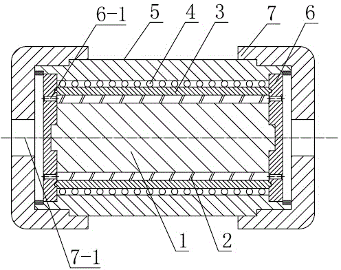
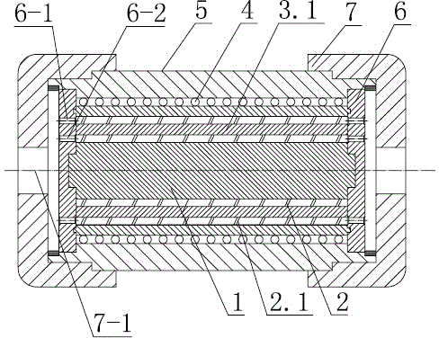
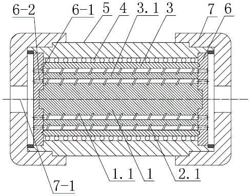
[0012] Referring to the accompanying drawings, a magneto-rheological valve structure includes a valve body 5, a valve body end cover 7, an oil inlet and outlet pan 6, an excitation coil 4 and a spool part, and the spool part includes: a central iron core 1, a spiral The retaining ring 2 and the sleeve 3, the central iron core 1, the spiral retaining ring 2 and the sleeve 3 are assembled concentrically in sequence, and the spiral retaining ring 2 divides the gap formed between the outer circle of the central iron core 1 and the inner circle of the sleeve 3 It has a spiral magneto-rheological fluid channel structure, the excitation coil 4 is arranged on the outer circle of the sleeve 3, and is arranged in the valve body 5, and the oil inlet and outlet pan 6 is arranged in the center of the valve body 5 On the end faces of the iron core 1 and the sleeve 3, the oil inlet and outlet holes 6-1 on the oil inlet and outlet pan 6 and the spiral retaining ring 2 divide the gap formed bet...


PUM


Abstract

The invention discloses a three-dimensional rotational flow magnetic gap magneto-rheological valve structure. The aims of lengthening an electromagnetic rheological fluid flowing path, improving the use rate of magnetic force lines, controlling the differential pressure of electromagnetic rheological fluid, saving energy and reducing the size of a magneto-rheological valve are achieved. According to the technical scheme, a valve element part in the structure comprises a center iron core, a spiral stopping ring and a sleeve, the center iron core, the spiral stopping ring and the sleeve are sequentially and concentrically installed in a sleeved mode to form a whole, a gap formed between the outer circle of the center iron core and the inner circle of the sleeve is divided by the spiral stopping ring into a spiral magneto-rheological liquid channel structure, a magnet exciting coil is arranged on the outer circle of the sleeve and arranged in a valve body, oil inlet-outlet discs are arranged on the end faces of the center iron core and the end faces of the sleeve, oil inlet-outlet holes in the oil inlet-outlet discs correspond to a spiral magneto-rheological liquid channel formed in the mode that the gap formed between the outer circle of the center iron core and the inner circle of the sleeve is divided by the spiral stopping ring, the valve body is installed in two valve body end covers, and oil holes in the valve body end covers are communicated with the oil holes in the oil inlet-outlet discs in the valve body. The three-dimensional rotational flow magnetic gap magneto-rheological valve structure has the advantages that the energy is saved, and the size of the magneto-rheological valve is small.

Description

technical field [0001] The invention relates to a hydraulic control valve, in particular to the improvement of a liquid flow channel of a magneto-rheological valve, in particular to a structure of a three-dimensional swirling magnetic gap magneto-rheological valve. Background technique [0002] Compared with traditional hydraulic control valves, magnetorheological valves control the flow of magnetorheological fluid through the valve by controlling the magnitude of the excitation coil current, without moving mechanical parts. Compared with traditional mechanical valves, magnetorheological fluid control valves Simple structure, small size, easy to control, fast response, low working noise, wear resistance, high reliability and low cost. The hydraulic control range of magneto-rheological valves has its own limitations. One is that the flow direction of the magnetorheological fluid in the magnetic gap space must be perpendicular to the direction of the magnetic field; the secon...

Claims


Application Information

Patent Timeline
Patent Type & Authority Patents(China)
IPC IPC(8): F15B13/02
Inventor 刘丹丹赵灿汤春瑞徐益民张桂凤郭智涛郭智波
Owner HEILONGJIANG UNIVERSITY OF SCIENCE AND TECHNOLOGY
Why Eureka
Try Eureka