
Micro-oil ignition system and method for w-type flame boiler

A micro-oil ignition and flame technology, which is applied in the combustion method, combustion type, burner for burning powder fuel, etc., can solve the problems of low fuel saving rate, system explosion, complicated operation, etc., to ensure safety and reliability. , The effect of improving fuel saving rate and low operating cost

Active Publication Date: 2016-03-30
HANGZHOU ZHEDA TIANYUAN SCI & TECH
View PDF8 Cites 0 Cited by
  • Summary
  • Abstract
  • Description
  • Claims
  • Application Information

AI Technical Summary

Problems solved by technology

[0005] These technologies generally have problems such as low fuel saving rate, complicated operation, failure of the pulverizing system, and fire extinguishing in the furnace. , the pulverizing system for grinding anthracite is still used, which causes the system to operate under design conditions, which is likely to cause failure of the pulverizing system, and even cause the system to explode in severe cases
In addition, some power plants have adopted the conventional micro-oil ignition technology, but this technology is generally used to ignite coal with high volatile content, but it is directly used to ignite anthracite with low volatile content, which may cause it to be difficult to ignite quickly and burn stably. Shortcomings, resulting in boiler flameout or still need to invest a lot of oil guns for ignition and stable combustion

Method used


Image

  • Micro-oil ignition system and method for w-type flame boiler
  • Micro-oil ignition system and method for w-type flame boiler

Examples


Embodiment Construction

[0022] The present invention will be further described below in conjunction with accompanying drawings and examples.

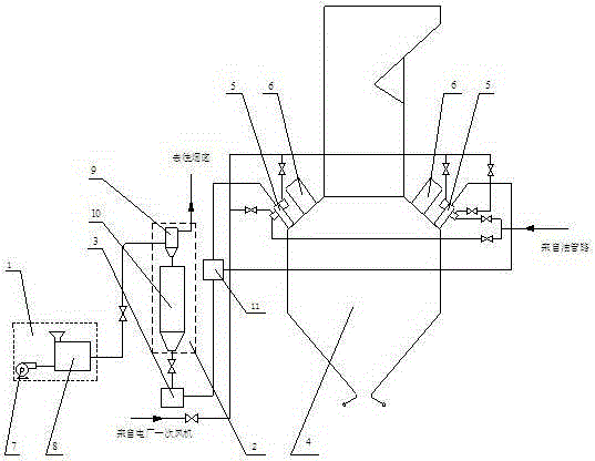
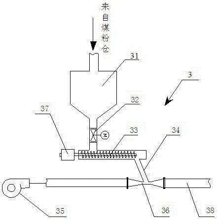
[0023] Such as figure 1 with figure 2 As shown, the micro-oil ignition system suitable for W-type flame boilers includes pulverized coal preparation system 1, pulverized coal storage system 2, pulverized coal delivery system 3, boiler body 4, pulverized coal burner for micro-oil ignition pulverized coal, and primary burner 6 , pulverized coal distributor 11, pulverized coal preparation system 1 includes blower 7 and coal mill 8, pulverized coal storage system 2 includes bag filter 9 and pulverized coal bin 10, pulverized coal conveying system 3 includes intermediate pulverized bin 31, Electric valve 32, powder conveying auger 33, blanking pipe 34, Roots blower 35, air powder mixer 36, powder conveying auger motor 37, primary air supply pipe 38, blower 7, coal mill 8, bag type Dust collector 9, pulverized coal bin 10, pulverized coal conveying system 3, pulv...


PUM


Abstract

The invention discloses a micro-oil ignition system and a micro-oil ignition method applicable to a W-type flame boiler. The micro-oil ignition system comprises a pulverized coal preparation system, a pulverized coal storage system, a pulverized coal conveying system, a boiler body, a micro-oil ignition pulverized coal burner, an original burner and a pulverized coal distributor, wherein the pulverized coal preparation system, the pulverized coal storage system, the pulverized coal conveying system, the pulverized coal distributor, the micro-oil ignition pulverized coal burner and the boiler body are sequentially connected; the micro-oil ignition pulverized coal burner is arranged on the front and rear arches of the boiler body; the pulverized coal conveying system comprises a middle pulverized coal chamber, an electric valve, a pulverized coal conveying auger, a blanking pipe, a Roots blower, an air and pulverized coal mixer, a pulverized coal conveying auger motor and a primary air supply pipe. An original pulverized coal preparation system of a power plant is not changed, so that the safety and reliability of the original pulverized coal preparation system are ensured, and the micro-oil ignition system has the advantages of high oil saving rate, simplicity, low equipment investment, low operation cost and the like, can be widely applied to ignition and low-load steady burning processes of the W-type flame boiler, and has certain market competitiveness.

Description

technical field [0001] The invention relates to a micro-oil ignition system, in particular to a micro-oil ignition system suitable for a W-shaped flame boiler and a method thereof. Background technique [0002] The total amount of coal resources in my country is abundant. According to statistics, the national predicted coal reserves are 2.6 trillion tons, of which anthracite accounts for 12% of the national coal reserves and is widely distributed. There are more than 20 provinces in the country that have anthracite resources to varying degrees. Anthracite usually has the characteristics of high degree of coalification, low volatile matter content and high ash content, and the high degree of coalification also makes its lithofacies structure compact and stable, with small porosity and low reactivity. Therefore, in the actual combustion process, anthracite coal There are often problems of difficulty in ignition, stable combustion, and burnout. The required ignition temperature...

Claims


Application Information

Patent Timeline
Patent Type & Authority Patents(China)
IPC IPC(8): F23D1/00F23K1/00F23K3/02
Inventor 谢辉王进卿池作和游国平
Owner HANGZHOU ZHEDA TIANYUAN SCI & TECH
Learn More