High-temperature smoke heat exchanger for urea pyrolytic process
A high-temperature flue gas and heat exchanger technology, which is applied in the field of high-temperature heat exchangers, can solve the problems of easy fouling and damage of heat exchangers, and achieve the effects of reasonable load-bearing distribution, avoiding cracking, and ensuring stable connection.
- Summary
- Abstract
- Description
- Claims
- Application Information
AI Technical Summary
Problems solved by technology
Method used
Image
Examples
Embodiment 1
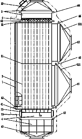
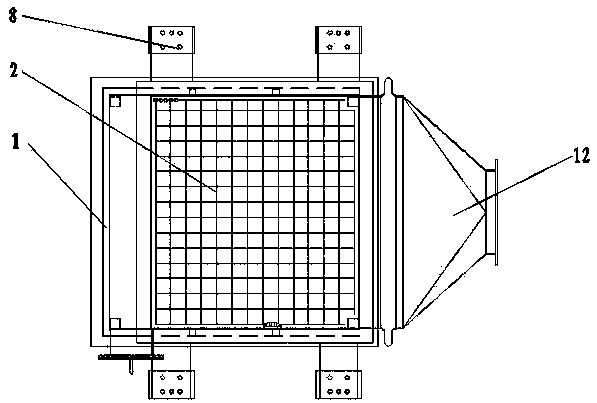
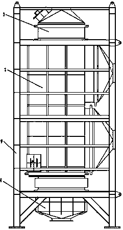
[0030] Embodiment one: see figure 1 and figure 2 As shown, a high-temperature flue gas heat exchanger used in the urea pyrolysis process adopts a shell-and-tube heat exchange structure, including a shell 1, a heat exchange tube bundle 2 set in the shell 1, and a heat exchange tube bundle 2 set in the shell 1. The upper shell-side inlet 11 and the shell-side outlet 12, the heat exchange tube bundle 2 are vertically arranged, and the upper and lower ends of the shell 1 are connected with the heat exchange tube bundle 2, and an upper tube box 3 and a lower tube box 4 are arranged. A heat insulation structure 5 is arranged on the tube sheet 31 , and the upper ends of each heat exchange tube pass through the heat insulation structure 5 and communicate with the upper tube box 3 . The inner side of the upper tube box 3 and the inner side of the upper head 32 are provided with an insulating layer. The inlet and outlet of the shell side are located on the same side of the shell 1, t...
Embodiment 2
[0036] Embodiment 2: A urea pyrolysis ammonia production device for denitrification, including a flue gas running pipeline, an air running pipeline, a urea pyrolysis chamber, and a heat exchanger. The high-temperature flue gas in the flue gas running pipeline Exchange heat with the air in the air running pipeline at the heat exchanger, and the heated air enters the urea pyrolysis chamber as a heat source for urea pyrolysis, wherein the heat exchanger adopts the high-temperature flue gas heat exchanger of Embodiment 1 , the flue gas running pipeline is connected to the tube side of the high-temperature flue gas heat exchanger, and the air running pipeline is connected to the shell side of the high-temperature flue gas heat exchanger.
[0037] According to the needs, install fans, air ducts, and air flow regulating doors in the air running pipeline; set flue gas flow regulating doors, flue gas pipes, and induced draft fans in the flue gas running pipeline; set urea spray guns in ...
Embodiment 3
[0038] Embodiment 3: A high-temperature flue gas heat exchanger for urea pyrolysis process adopts a shell-and-tube heat exchange structure, including a shell, a heat exchange tube bundle set in the shell, and a shell side set on the shell The inlet and outlet, the heat exchange tube bundles are arranged vertically, the upper and lower tube boxes are connected with the heat exchange tube bundles at the upper and lower ends of the shell, and the upper tube box and the lower tube box are arranged. It passes through the heat insulation structure and communicates with the upper pipe box. The inner side of the upper tube box and the inner side of the upper head are provided with an insulating layer.
[0039] In this embodiment, the shell-side inlet and the shell-side outlet are located on both sides of the shell, and two sets of baffles are arranged on the heat exchange tube bundle, the shell-side inlet is located under the lower baffle, and the shell-side outlet is located at the u...
PUM
| Property | Measurement | Unit |
|---|---|---|
| thickness | aaaaa | aaaaa |
| thickness | aaaaa | aaaaa |
Abstract
Description
Claims
Application Information
 - R&D
- Intellectual Property
- Life Sciences
- Materials
- Tech Scout
- Unparalleled Data Quality
- Higher Quality Content
- 60% Fewer Hallucinations
Browse by: Latest US Patents, China's latest patents, Technical Efficacy Thesaurus, Application Domain, Technology Topic, Popular Technical Reports.
© 2025 PatSnap. All rights reserved.Legal|Privacy policy|Modern Slavery Act Transparency Statement|Sitemap|About US| Contact US: help@patsnap.com


