
To-be-detected element locating device for detecting platform

A technology for testing platforms and components to be tested, applied in the direction of measuring devices, measuring instrument components, instruments, etc., can solve the problems that the positioning accuracy cannot be guaranteed, and the detection data cannot truly reflect the accuracy index of the workpiece to be tested, so as to achieve easy installation and operation Simple and guaranteed positioning accuracy

Inactive Publication Date: 2014-05-07
XIAMEN UNIV
View PDF6 Cites 6 Cited by
  • Summary
  • Abstract
  • Description
  • Claims
  • Application Information

AI Technical Summary

Problems solved by technology

At present, for high-precision components such as aspheric surfaces, some detection methods mainly measure the busbar or the direction perpendicular to the busbar. If the position of the workpiece deviates too much from the ideal detection direction, the detection data cannot truly reflect the measurement. Various precision indicators of the workpiece
However, the current positioning methods of many detection platforms are manual sensory adjustments, so the positioning accuracy cannot be guaranteed

Method used


Image

  • To-be-detected element locating device for detecting platform
  • To-be-detected element locating device for detecting platform

Examples


Embodiment Construction

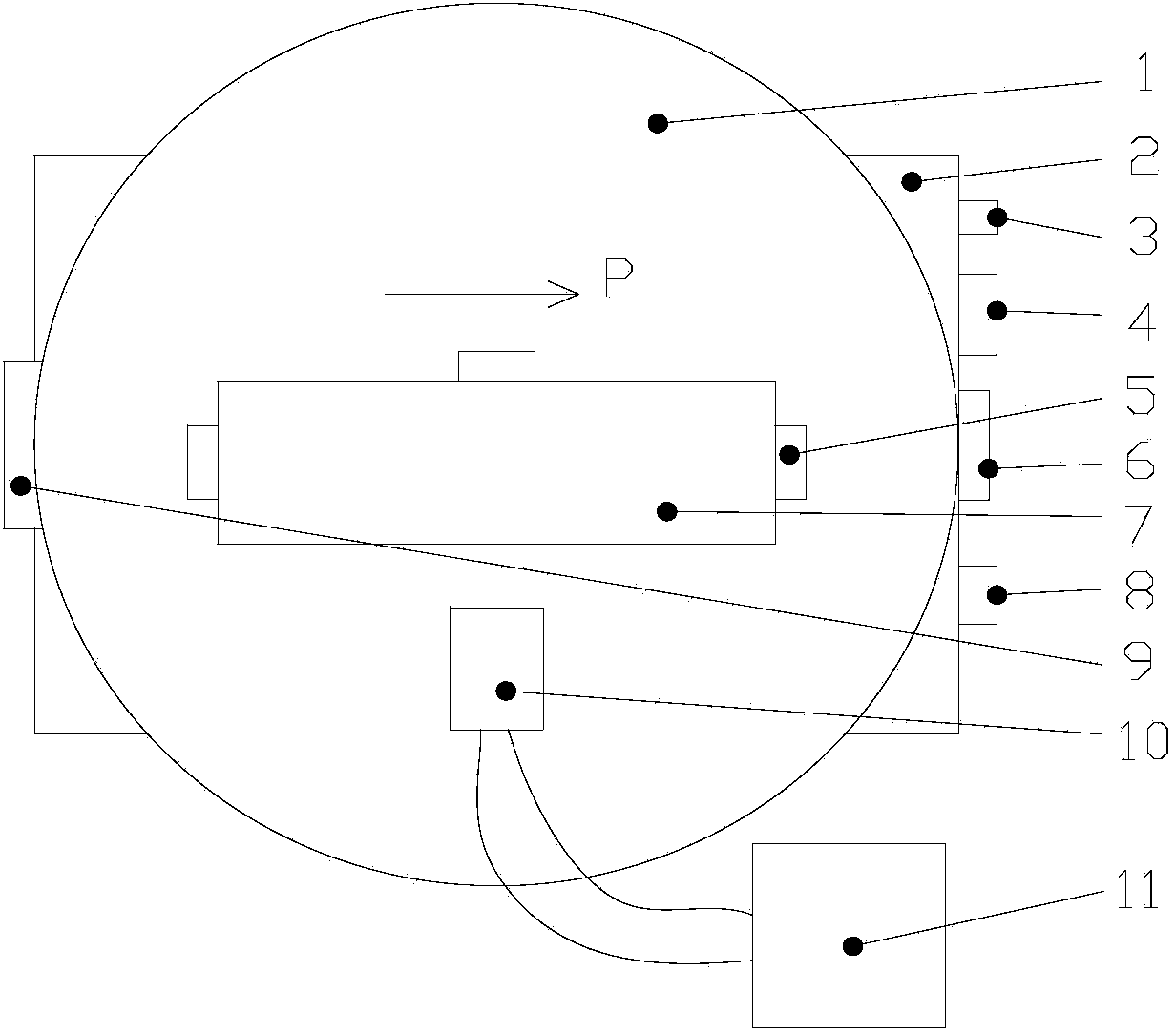
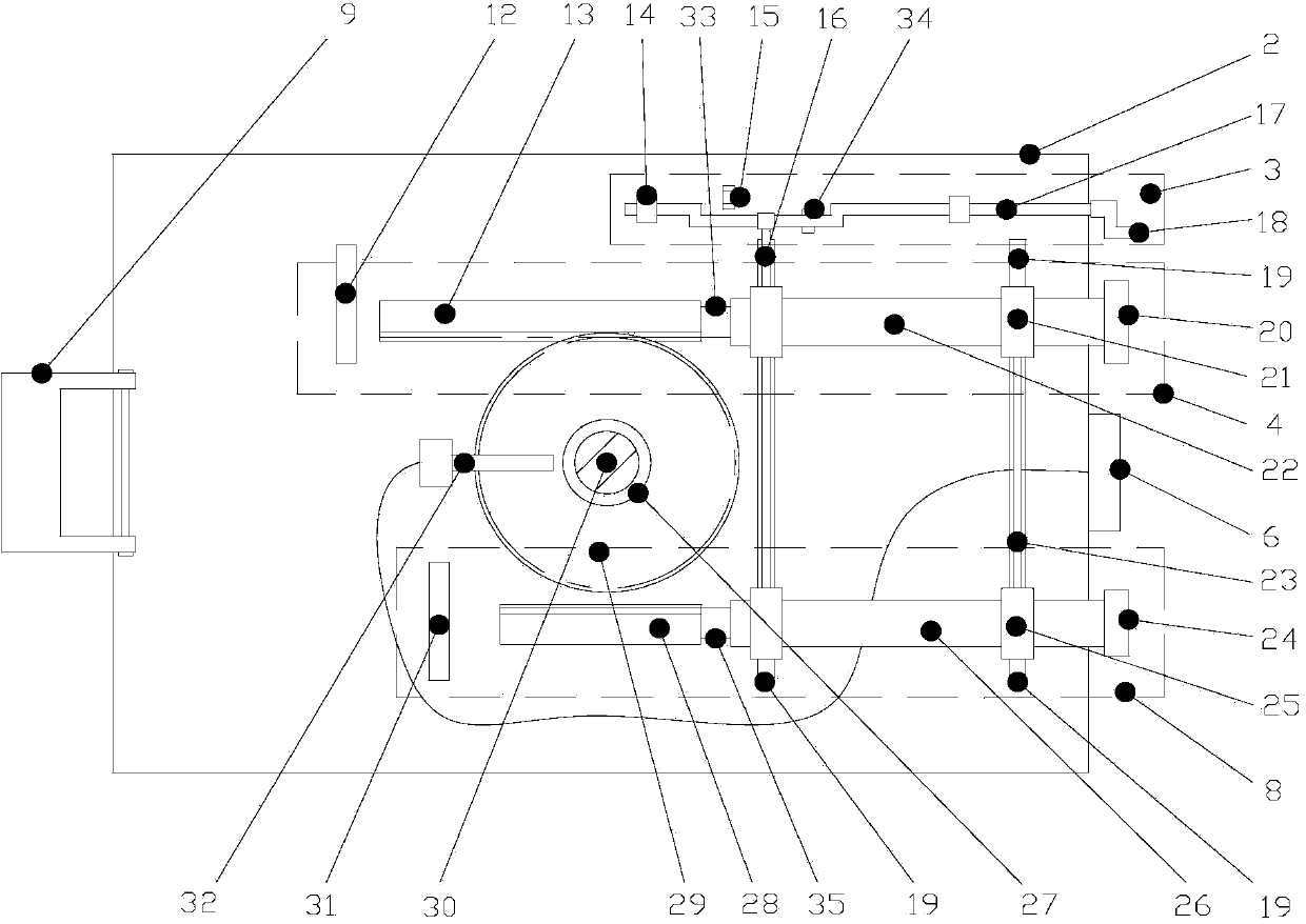
[0014] like figure 1 and 2 As shown, the embodiment of the present invention is provided with a rotating platform 1, a rotating base 2, a shift mechanism 3, a coarse adjustment mechanism 4, a rectangular magnet block 5, an angle display 6, a fine adjustment mechanism 8, a fixed block 9, and a non-contact sensor 10 , PC 11.

[0015] The rotating platform 1 is connected with the rotating base 2 through a shaft 30, and the shaft 30 is respectively connected with the coarse adjustment mechanism 4 and the fine adjustment mechanism 8 through the gear 29, the coarse adjustment rack 13 and the fine adjustment rack 28, and the shaft 30 is fixed with a circular The grating 27 and the circular grating 27 are used to detect the rotation angle of the shaft 30 and display it through the angle display 6; the coarse adjustment mechanism 4 and the fine adjustment mechanism 8 are connected by a connecting rod 23, and the coarse adjustment mechanism 4 and the fine adjustment mechanism 8 can be ...


PUM


Abstract

The invention provides a to-be-detected element locating device for a detecting platform and relates to an element locating device. The to-be-detected element locating device is provided with a rotating platform, a rotating base, a shift mechanism, a rough adjustment mechanism, a rectangular magnet, an angle displayer, a fine adjustment mechanism, a fixing block, a non-contact type sensor and a PC. The shift mechanism is provided with a crankshaft, a crankshaft fixing base, an upper shift limiting block, a lower shift limiting block and a handle. The rough adjustment mechanism is provided with a rough adjustment screw rod nut, a rough adjustment screw rod, a rough adjustment screw rod nut base, a rough adjustment rack, a rough adjustment knob and a rough adjustment limiting block. The structure of the fine adjustment mechanism is the same as that of the rough adjustment mechanism. The screw pitch between a fine adjustment screw rod nut and a fine adjustment screw rod is far smaller than the screw pitch between the rough adjustment screw rod nut and the rough adjustment screw rod. The adjustment range of the rough adjustment mechanism is from -5 degrees to 5 degrees, and the adjustment range of the fine adjustment mechanism is from -1 degree to 1 degree. The placing angle of work-pieces can be accurately adjusted, installation is simple, operation is simple, fine adjustment and rough adjustment can be carried out, the locating accuracy can be ensured, the detection precision of the detecting platform is not influenced, and the locating device can be used together with most detecting platforms.

Description

technical field [0001] The invention relates to a component positioning device, in particular to a component positioning device for a testing platform which can precisely adjust the placement angle of a workpiece. Background technique [0002] The accuracy of parts is an important basis for the application of parts, and the accuracy of parts is mainly obtained by inspection, and the detection error is an important factor affecting the evaluation of part accuracy. At present, for high-precision components such as aspheric surfaces, some detection methods mainly measure the busbar or the direction perpendicular to the busbar. If the position of the workpiece deviates too much from the ideal detection direction, the detection data cannot truly reflect the measurement. Various accuracy indicators of the workpiece. However, the current positioning methods of many detection platforms are manual sensory adjustments, so the positioning accuracy cannot be guaranteed. Chinese patent...

Claims


Application Information

Patent Timeline
Patent Type & Authority Applications(China)
IPC IPC(8): G01D11/00
Inventor 郭隐彪张东旭杨平杨旭
Owner XIAMEN UNIV
Learn More