
Particulate matter sensor unit

A particle sensor and sensor technology, which is applied in individual particle analysis, particle and sedimentation analysis, instruments, etc., can solve the problem of low detection accuracy of differential pressure sensor

Active Publication Date: 2014-05-07
HYUNDAI MOTOR CO LTD +2
View PDF6 Cites 7 Cited by
  • Summary
  • Abstract
  • Description
  • Claims
  • Application Information

AI Technical Summary

Problems solved by technology

[0005] In the future, the differential pressure sensor will no longer be used to detect the damage of the DPF according to the exhaust gas regulations. In addition, the detection accuracy of the differential pressure sensor is also low

Method used


Image

  • Particulate matter sensor unit
  • Particulate matter sensor unit
  • Particulate matter sensor unit

Examples


Embodiment Construction

[0043] Reference will now be made in detail to various embodiments of the invention, examples of which are illustrated in the accompanying drawings and described below. While the invention has been described in conjunction with exemplary embodiments, it will be understood that present description is not intended to limit the invention to those exemplary embodiments. On the contrary, the invention is intended to cover not only the exemplary embodiments, but also various alternatives, modifications, equivalents and other embodiments, which may be included within the spirit and scope of the invention as defined by the appended claims.

[0044] Exemplary embodiments of the present invention will be described in detail below with reference to the accompanying drawings.

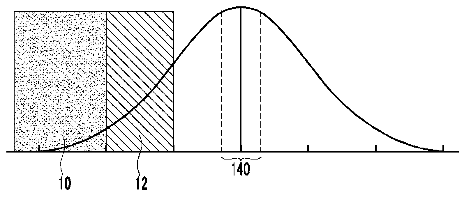
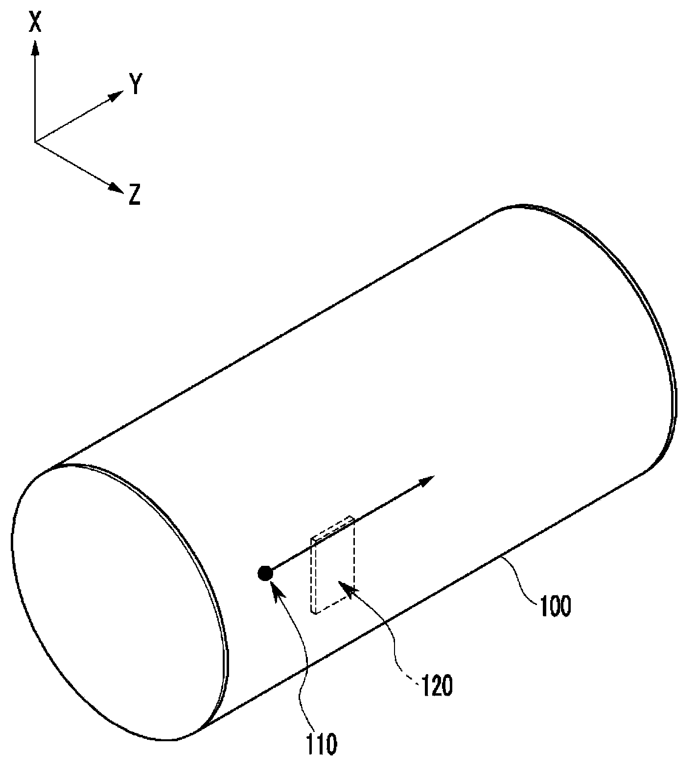
[0045] figure 1 For a graph showing the amount of particulate matter obtained in a diesel particulate filter according to an exemplary embodiment of the present invention, figure 2 An internal perspective view s...


PUM

PropertyMeasurementUnit
diameteraaaaaaaaaa
widthaaaaaaaaaa
distanceaaaaaaaaaa

Abstract

Disclosed is a particulate matter sensor unit. A particulate sensor apparatus may include an exhaust line through which exhaust gas flows, and a sensor that may be disposed at one side in the exhaust line and generates electrical charges when a particulate passes near vicinity of the sensor, wherein an electrode portion may be formed on a front surface of the sensor facing the particulate.

Description

[0001] Cross References to Related Applications [0002] This application claims priority from Korean Patent Application No. 10-2012-0119183 filed on Oct. 25, 2012, the entire contents of which are hereby incorporated by reference for all purposes. technical field [0003] The present invention relates to a particle sensor unit which accurately and efficiently detects damage to a particle filter which filters particulate matter (PM) contained in exhaust gas and transmits a detection signal to a control part. Background technique [0004] Diesel vehicles have used a diesel particulate filter (DPF) in order to reduce PM therein, and a differential pressure sensor to detect the amount of PM acquired in the diesel particulate filter. [0005] In the future, the differential pressure sensor will no longer be used to detect the damage of the DPF according to the exhaust gas regulations, and the detection accuracy of the differential pressure sensor is also low. [0006] The infor...

Claims


Application Information

Patent Timeline
Patent Type & Authority Applications(China)
IPC IPC(8): G01N15/10
CPCG01M15/102G01N15/0656F01N2560/05F01N11/00G01N27/22
Inventor 李津夏S·林张根豪全国镇郑珍宇
Owner HYUNDAI MOTOR CO LTD
Learn More