Anti-interference parameter integration testing device for ultra-high voltage line

A line parameter, integrated testing technology, applied in the direction of measuring devices, measuring electrical variables, measuring current/voltage, etc., can solve the problems of unguaranteed accuracy, safety, hidden dangers, etc., and achieve the effect of simple wiring

Inactive Publication Date: 2014-05-07
SHANGHAI MUNICIPAL ELECTRIC POWER CO +2
View PDF3 Cites 8 Cited by
  • Summary
  • Abstract
  • Description
  • Claims
  • Application Information

AI Technical Summary

Problems solved by technology

[0002] With the increasing scale of UHV power grid construction and the significant increase in grid density, the electromagnetic environment at the line parameter test site has deteriorated. The power frequency electrostatic induction voltage at the test site has reached tens of kilovolts, and the electromagnetic induction current has reached tens or even hundreds of amperes. , its amplitude and phase change with the load of the power grid, so that the accuracy of the traditional method of using power frequency power supply to test line parameters cannot be guaranteed, the wiring and operation are cumbersome, and there are potential safety hazards. The measurement of frequency parameters has caused great difficulties

Method used


Image

  • Anti-interference parameter integration testing device for ultra-high voltage line
  • Anti-interference parameter integration testing device for ultra-high voltage line

Examples


Embodiment Construction

[0021] The present invention will be described in detail below in conjunction with the accompanying drawings and specific embodiments. This embodiment is carried out on the premise of the technical solution of the present invention, and detailed implementation and specific operation process are given, but the protection scope of the present invention is not limited to the following embodiments.

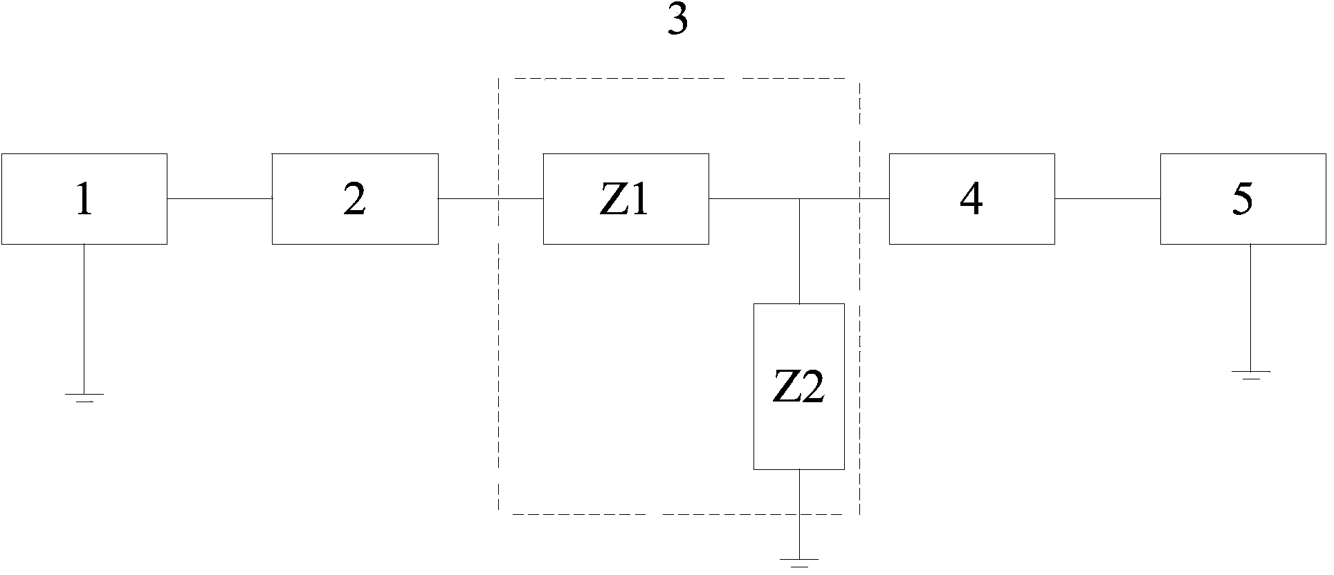
[0022] like figure 1 As shown, an integrated test device for anti-interference UHV line parameters is used for integrated measurement of power frequency parameters of the UHV line 4 to be measured. The device includes a different frequency measurement module 1, a measurement wiring automatic conversion module 2, a serial Parallel suppressed impedance module 3 and opposite-end GPS synchronous measurement module 5, the inter-frequency measurement module 1, measurement wiring automatic conversion module 2, series-parallel suppressed impedance module 3, measured UHV line 4 and opposite-en...


PUM


Abstract

The invention relates to an anti-interference parameter integration testing device for an ultra-high voltage line. The anti-interference parameter integration testing device is used for performing integrated measurement on power frequency parameters of a measured ultra-high voltage line. The device comprises a pilot frequency measurement module, a measuring and wiring automatic switching module, a series and parallel impedance suppression module and an opposite-end GPS synchronous measurement module. The pilot frequency measurement module is used for performing digital separation and power frequency parameter calculation of a power frequency interference signal and a pilot frequency signal on a measured signal. The measuring and wiring automatic switching module is connected with the pilot frequency measurement module and used for automatically switching internal wiring modes according to the power frequency parameters to be measured. The measuring and wiring automatic switching module and the measured ultra-high voltage line are respectively connected with the series and parallel impedance suppression module which is used for relieving the influence on measurement by electrostatic induction voltage and induced current. The opposite-end GPS synchronous measurement module is connected with the measured ultra-high voltage line and is used for synchronously performing measurement of the physical quantity of the line at the other end of the measured ultra-high voltage line by means of GPS synchronization. Compared with the prior art, the anti-interference parameter integration testing device has the advantages that the device is of modular design, wiring is easy, and all tests can be completed as long as wiring is performed at a time.

Description

technical field [0001] The invention relates to a line parameter test device, in particular to an anti-interference ultra-high voltage line parameter integrated test device. Background technique [0002] With the increasing scale of UHV power grid construction and the significant increase in grid density, the electromagnetic environment at the line parameter test site has deteriorated. The power frequency electrostatic induction voltage at the test site has reached tens of kilovolts, and the electromagnetic induction current has reached tens or even hundreds of amperes. , its amplitude and phase change with the load of the power grid, so that the accuracy of the traditional method of using power frequency power supply to test line parameters cannot be guaranteed, the wiring and operation are cumbersome, and there are potential safety hazards. The measurement of frequency parameters has caused great difficulties. Contents of the invention [0003] The purpose of the presen...

Claims


Application Information

Patent Timeline
Patent Type & Authority Applications(China)
IPC IPC(8): G01R27/08G01R27/26
CPCG01R19/2513
Inventor 周行星郭森范毅黄华肖嵘
Owner SHANGHAI MUNICIPAL ELECTRIC POWER CO
Why Eureka
Try Eureka