
Ultrasonic diagnostic device

An ultrasonic diagnostic instrument and ultrasonic technology, applied in the directions of sonic diagnosis, infrasound diagnosis, and diagnosis, can solve the problems of troublesome disassembly and maintenance, inflexible change of the number of channels of the ultrasonic diagnostic instrument, etc., to achieve easy maintenance, meet anti-interference requirements, prevent the effect of interference

Active Publication Date: 2012-07-11
SHENZHEN MINDRAY BIO MEDICAL ELECTRONICS CO LTD +1
View PDF0 Cites 0 Cited by
  • Summary
  • Abstract
  • Description
  • Claims
  • Application Information

AI Technical Summary

Problems solved by technology

Once the ASIC is made, due to the high integration level, if it is found that the performance of individual channels affects the image quality after the whole machine is assembled, it is quite troublesome to disassemble and repair; and because the number of internal channels is fixed when the ASIC is designed, so in ultrasound It is very inflexible when the channel number requirements of the diagnostic instrument change

Method used


Image

  • Ultrasonic diagnostic device
  • Ultrasonic diagnostic device
  • Ultrasonic diagnostic device

Examples


Embodiment Construction

[0010] The features and advantages of the present invention will be described in detail with reference to the accompanying drawings.

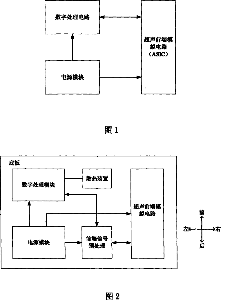
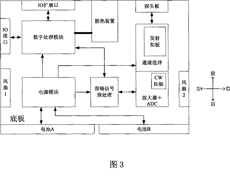
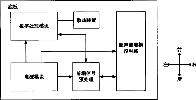
[0011] Please refer to figure 2 , the hardware circuit of the portable ultrasonic diagnostic instrument includes a bottom plate, an ultrasonic front-end analog circuit, a digital processing circuit and a power supply module. The ultrasonic front-end analog circuit is used to transmit ultrasonic waves and receive echoes for amplification and analog-to-digital conversion. The digital processing circuit mainly implements functions such as operating system loading, system control, image post-processing, user application interface, and external interface provision. The power module is used for It provides power for the ultrasonic front-end analog circuit and digital processing circuit, and the backplane provides the interconnection between various functional modules, and also realizes some other functions.

[0012] The power module is located on t...


PUM


Abstract

The invention discloses an ultrasonic diagnostic device comprising a base plate, an ultrasonic front end analog circuit, a digital processing circuit connected with the ultrasonic front end analog circuit and a power supply module for providing power supply for the ultrasonic front end analog circuit and the digital processing circuit, the ultrasonic front end analog circuit is of modular design,the digital processing circuit and the power supply module are positioned on one certain half edge of the base plate, and the ultrasonic front end analog circuit is positioned on the other half edge of the base plate. The ultrasonic diagnostic device of the invention adopts a modularization ultrasonic front end analog circuit, the assembling is convenient, the maintenance is easy, the subsequent performance upgrading of the ultrasonic diagnostic device is convenient, meanwhile the ultrasonic front end analog circuit is designed on the far ends of the power supply module and the digital processing circuit, so that the interferences from the power supply and the digital circuit can be prevented.

Description

【Technical field】 [0001] The invention relates to a portable ultrasonic diagnostic instrument. 【Background technique】 [0002] The hardware circuit of the portable ultrasonic diagnostic instrument is usually as follows figure 1 As shown, it includes the ultrasonic front-end analog circuit, the digital processing circuit (that is, the computer processing module) that processes and controls the echo signal of the ultrasonic front-end analog circuit, and the power supply module that provides power for the ultrasonic front-end analog circuit and the digital processing circuit. The ultrasonic front-end analog circuit is divided into two parts: transmitting and receiving. The transmitting generally adopts high voltage, while the receiving pursues low noise, so the performance requirements are very high. In the existing portable ultrasonic diagnostic instrument, the ultrasonic front-end analog circuit adopts ASIC to make a chip form, and adopts BGA package. Once the ASIC is made,...

Claims


Application Information

Patent Timeline
Patent Type & Authority Patents(China)
IPC IPC(8): A61B8/00
CPCG01S15/8906G01S7/52082G01S7/52096
Inventor 黄海涛何绪金关智勇刘国涛
Owner SHENZHEN MINDRAY BIO MEDICAL ELECTRONICS CO LTD
Learn More