Automatic driving control system and method

A technology of a control system and a control method, applied in the field of control, can solve problems such as chronic drift of vehicle performance, software development and verification, difficulty in field debugging and after-sales maintenance, control accuracy, and system response speed. The basic performance indicators of the control system are difficult to take into account.

Active Publication Date: 2014-05-07
TRAFFIC CONTROL TECH CO LTD
View PDF9 Cites 46 Cited by
  • Summary
  • Abstract
  • Description
  • Claims
  • Application Information

AI Technical Summary

Problems solved by technology

[0004] The traditional ATO system improves the control performance of ATO by directly adjusting the controller parameters. The vehicle is a time-delay system with a relatively large time constant and is sensitive to vehicle performance. Controller adaptability, control accuracy, system response speed, etc. It is already difficult to balance the basic performance indicators of the control system, and it is even more difficult to guarantee the comfort of automatic driving
Even if multiple sets of controller parameters are used, the dimensions available for adjustment are still limited, and most of the controller parameters are not intuitive and inconvenient to understand. The increase of controller parameters has caused great impact on software development and verification, on-site debugging, and after-sales maintenance. Difficulties
At the same time, with the accumulation of train running time, the performance of the vehicle will drift slowly over time, which will affect the control effect of the on-board controller, and the controller's control of the train will be more difficult to operate

Method used


Image

  • Automatic driving control system and method
  • Automatic driving control system and method
  • Automatic driving control system and method

Examples


Embodiment Construction

[0033] The specific implementation manners of the present invention will be further described in detail below in conjunction with the accompanying drawings and embodiments. The following examples are used to illustrate the present invention, but are not intended to limit the scope of the present invention.

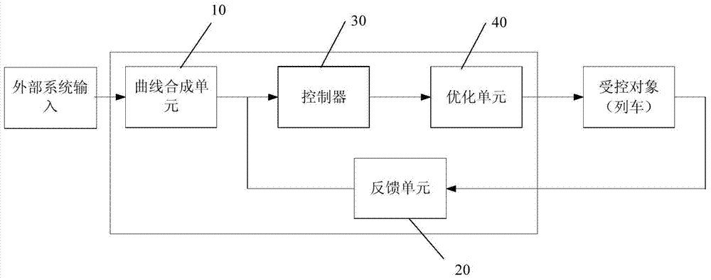
[0034] An embodiment of the present invention provides a control system for automatic driving, the schematic diagram of its composition architecture is as follows figure 2 shown, including:

[0035] Curve synthesis unit 10, feedback unit 20, controller 30 and optimization unit 40;

[0036] Wherein the curve synthesis unit 10 is used to calculate the target speed curve according to the conditions input by the external system;

[0037] The feedback unit 20 is used to collect the state information during the train operation;

[0038] The controller 30 is used to formulate control instructions for the train according to the target speed curve and the state information fed ...


PUM


Abstract

The invention discloses an automatic driving control system and method. The control system comprises a curve synthesis unit, a feedback unit, a controller and an optimization unit, wherein the curve synthesis unit is used for calculating an object speed curve according to a condition inputted by an external system; the feedback unit is used for acquiring state information during the operation process of a train; the controller is used for making a train control instruction according to the object speed curve and the sate information fed back by the feedback unit; and the optimization unit is used for optimizing the control instruction outputted by the controller by use of an instruction optimization strategy and a relation matrix combined and constructed by conditions to obtain an optimized control instruction. According to the invention, through increasing optimization units, multi-target data is obtained, i.e., multiple parameters are obtained, and the object speed curve obtained through calculating by the curve synthesis unit is formed, the control instruction is obtained through combination with the state information which is fed back, and the control instruction is optimized, so that in a specific scene, self-adaptive automatic driving control is realized, the control of a vehicle-mounted controller is facilitated, and the control effects are improved.

Description

technical field [0001] The invention relates to the field of control technology, in particular to a control system and method for automatic driving. Background technique [0002] At present, the on-board signal equipment of most domestic subway lines has realized manned automatic driving. In the manned automatic driving mode, the automatic train protection system (ATP) is responsible for protecting the safety of the train, and the automatic train driving system (ATO) is responsible for the interval during the train operation. Run and pitstop controls. Under the protection of ATP, automatic driving can reduce the labor intensity of drivers, improve train operation efficiency, shorten subway operation intervals, and improve parking accuracy. [0003] As a standard control system, a typical ATO system architecture is as follows figure 1 As shown, the control system includes: the target curve calculation unit 01 calculates the target amount of speed according to the input cond...

Claims


Application Information

Patent Timeline
Patent Type & Authority Applications(China)
IPC IPC(8): G05D1/02
Inventor 肖骁
Owner TRAFFIC CONTROL TECH CO LTD
Why Eureka
Try Eureka