Contrast pyramid image fusion method based on area

A technology of pyramid image and fusion method, which is applied in image enhancement, image data processing, graphic image conversion, etc., can solve the problems of loss of image details, image contrast reduction, etc., and achieve good visual effects

Inactive Publication Date: 2014-05-07
GRADUATE SCHOOL OF THE CHINESE ACAD OF SCI GSCAS
View PDF1 Cites 15 Cited by
  • Summary
  • Abstract
  • Description
  • Claims
  • Application Information

AI Technical Summary

Problems solved by technology

[0006] The purpose of the present invention can meet the visual characteristics of the human eye to the greatest extent, provide a simple and efficient region-based contrast pyramid image fusion method that does not depend on any shooting parameters, and solve the loss of image details in the prior art and reduce the contrast of the image technical issues,

Method used


Image

  • Contrast pyramid image fusion method based on area
  • Contrast pyramid image fusion method based on area
  • Contrast pyramid image fusion method based on area

Examples


specific Embodiment approach

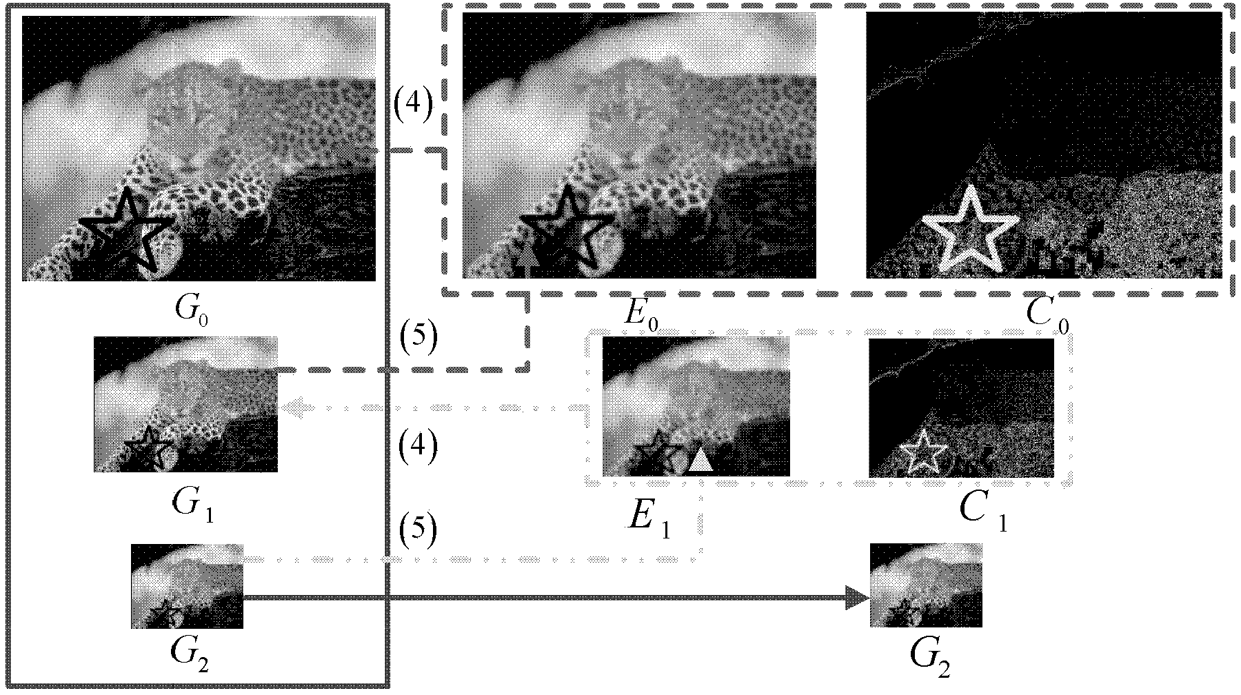
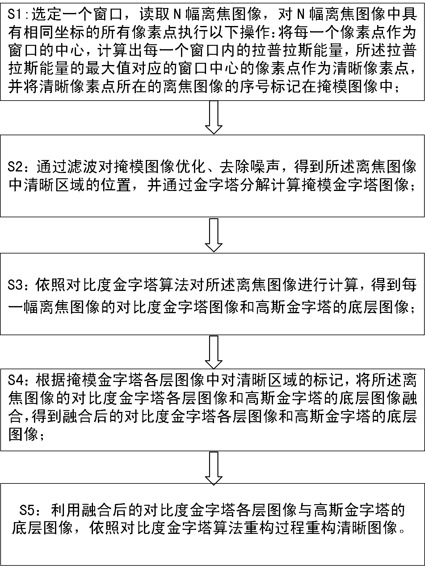
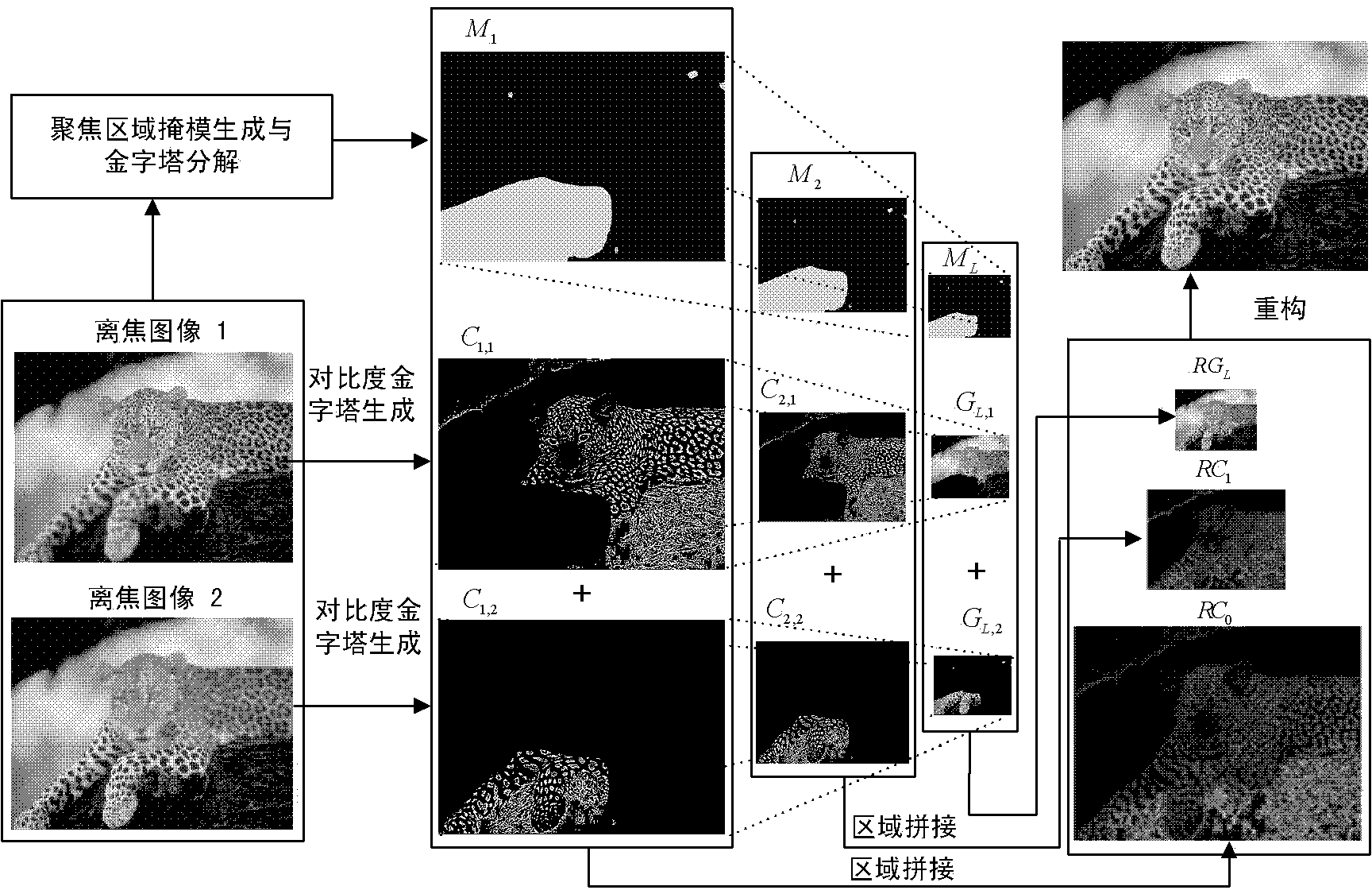
[0035] Step S1: Select a window, read N defocused images, perform the following operations on all pixels with the same coordinates in N defocused images: take each pixel as the center of the window, and calculate the Laplace energy, the pixel point in the center of the window corresponding to the maximum value of the Laplace energy is regarded as a clear pixel point, and the sequence number of the defocused image where the clear pixel point is located is marked in the mask image. The specific implementation is as follows:

[0036] Calculate the current pixel of each source image (defocused image), and the calculation of the Laplace energy EOL(x, y) is as follows:

[0037] EOL ( x , y ) = Σ x ∈ ( 1 , W ) ...


PUM


Abstract

The invention provides a contrast pyramid image fusion method based on an area. The method is characterized by utilizing a plurality of out-of-focus images to obtain a sharp image. The method is characterized by, to begin with, utilizing Laplace energy in an image window as measurement for showing whether the area is clear or not; obtaining positions of clear pixel points in each image; marking the positions of the clear pixel points in a mask image; then carrying out optimization operation on the mask image to obtain an accurate position of the clear area in the image; fusing each layer of image of a contrast pyramid with a ground floor image according to the marked clear area in a mask image pyramid; and establishing a completely clear image by utilizing the fused contrast pyramid and the ground floor image. The multi-focus image fusion algorithm can be applied to the processing of criminal investigation images, medical microscopic images, and does not rely on any camera parameters.

Description

technical field [0001] The invention belongs to the field of image processing, and relates to a method of using a mask map to guide the fusion of a contrast pyramid and an underlying image, and obtaining a full-clear image through reconstruction. Background technique [0002] There is a disadvantage of high-power optical lenses (such as microscopes): the order of magnitude of depth of field is generally 10 -3 m or smaller, and the higher the magnification, the smaller the depth of field. This leads to a consequence: when shooting a three-dimensional object, only a small part of an image with a large magnification is clear, while other areas are blurred. Such an image is called a defocused image. [0003] In the field of biological and medical research, when researchers use a microscope to observe tissue cells, due to the limitation of the depth of field, only a small part of the image presented by the microscope is clear, and the overall clear image of the observed object c...

Claims


Application Information

Patent Timeline
Patent Type & Authority Applications(China)
IPC IPC(8): G06T5/50G06T3/40
Inventor 焦建彬祝耀华叶齐祥
Owner GRADUATE SCHOOL OF THE CHINESE ACAD OF SCI GSCAS
Why Eureka
Try Eureka