Cooling device for a fluid flow machine

A fluid machinery and internal cooling technology, applied in gas turbine devices, mechanical equipment, jet propulsion devices, etc., can solve problems such as material defects, poor casting, and high cost, and achieve good thermal interaction and improve the effect of thermal interaction.

Inactive Publication Date: 2014-05-07
SIEMENS AG
View PDF10 Cites 1 Cited by
  • Summary
  • Abstract
  • Description
  • Claims
  • Application Information

AI Technical Summary

Problems solved by technology

This material is usually relatively expensive and can also be poorly cast, which leads to material defects

Method used


Image

  • Cooling device for a fluid flow machine
  • Cooling device for a fluid flow machine

Examples


Embodiment Construction

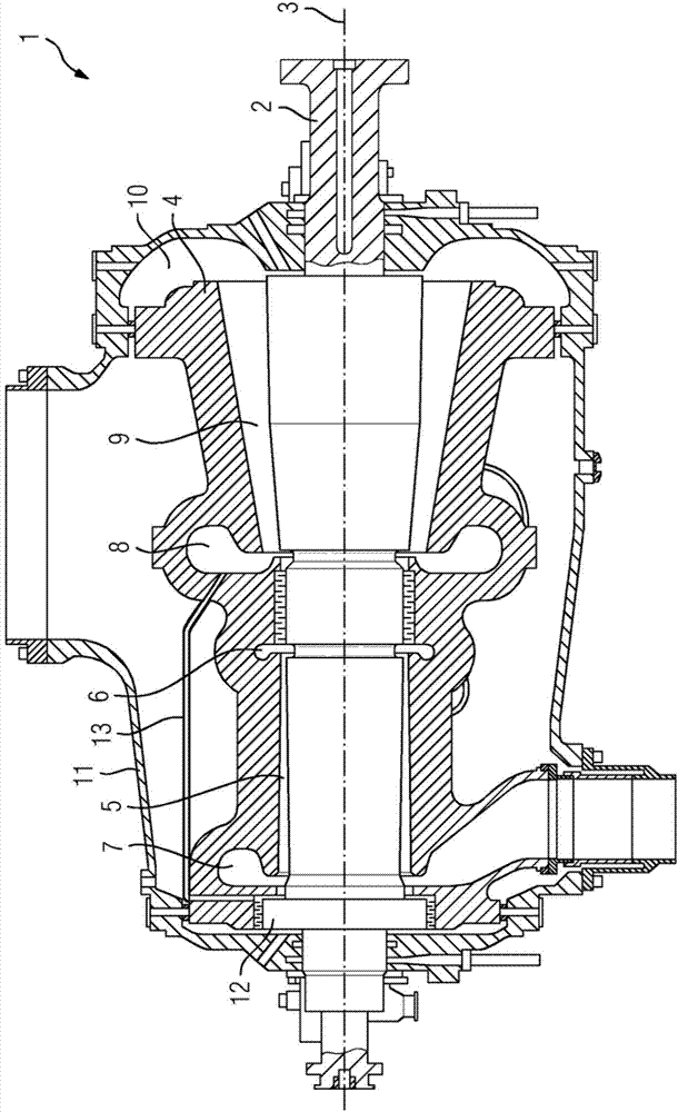
[0018] figure 1 A steam turbine 1 is shown as an embodiment of a fluid machine. The steam turbine 1 basically comprises a rotor 2 which is mounted rotatably about an axis of rotation 3 . An inner housing 4 is arranged around the rotor 2 , a first flow channel 5 , which can also be referred to as a high-pressure flow region, is formed between the inner housing 4 and the rotor 2 . The flow direction of the first flow channel 5 is in accordance with figure 1 The view is shown to the left. During operation, steam flows via the high-pressure live steam region 6 through the inner housing 4 into the first flow channel 5 . The steam flowing in in the first flow channel 5 via the high-pressure live steam area 6 is cooled in the direction of flow and leaves the steam turbine 1 via the high-pressure outflow area 7 and, after the intermediate superheating stage, is fed into the steam turbine again via the medium-pressure inflow area 8 , that is, delivered to the second flow channel 9 ...


PUM


Abstract

The invention relates to a fluid flow machine, in particular a steam turbine (1) having a piston-equalizing line (13) which conducts a vapor from a fresh vapor region of a second flow duct (9) to a thrust-equalizing piston (12), wherein the surface of the piston-equalizing line is enlarged, and the inner surface of the piston-equalizing line (13) is enlarged.

Description

technical field [0001] The present invention relates to a fluid machine comprising a rotor rotatably mounted around an axis of rotation, an inner casing arranged around the rotor, an outer casing arranged around the inner casing, wherein a rotor and an inner casing are arranged There is a first flow area and a second flow area formed in the opposite flow direction relative to the first flow area, wherein the rotor has a thrust balancing piston, wherein the piston balancing line is formed for the connection between the inner housing and the thrust balancing piston transport steam. Background technique [0002] In fluid machines, for example in steam turbines, hot live steam with a relatively high thermal energy is converted into rotational energy of a rotor. This takes place in the flow channels formed by the guide vanes and rotor blades. Today's steam turbines have steam temperatures above 600°C. Such high temperatures place increased demands on the materials to be used. ...

Claims


Application Information

Patent Timeline
Patent Type & Authority Applications(China)
IPC IPC(8): F02C7/141F01D3/02F01D25/26
CPCF05D2260/2322F01D3/02F01D25/26F02C7/141F05D2220/31F05D2260/213F05D2260/22141F05D2260/2214F01D3/04
Inventor 克里斯托夫·克斯特纳鲁道夫·波特
Owner SIEMENS AG
Why Eureka
Try Eureka