injection mold

An injection mold and moving template technology, applied in the field of injection molds with a secondary ejection mechanism, can solve the problems of difficulty in demolding, affecting the quality of parts, increasing the load of the secondary ejection mechanism, etc., so as to reduce structural design and production. Processing difficulty, enhanced movement stability, overall weight reduction effect

Active Publication Date: 2016-05-11
SHENZHEN SKYWORTH PRECISION TECH
View PDF3 Cites 3 Cited by
  • Summary
  • Abstract
  • Description
  • Claims
  • Application Information

AI Technical Summary

Problems solved by technology

Therefore, in the process of injection mold opening and ejection, the secondary ejection mechanism needs to overcome huge resistance, especially some large parts (for example, flat panel TV frame) need to use pusher plate when demolding, this kind of The ejection structure once again increases the load of the secondary ejection mechanism, which is likely to cause difficulty in demoulding and jamming in the actual production process, thereby affecting the quality of the part and reducing production efficiency
In addition, for some deep bone parts, the structure of the secondary ejection mechanism is complicated, and the mold used with it has a large thickness, complex structure, and difficult installation. The entire set of molds requires a large amount of processing and high production costs.

Method used


Image

  • injection mold
  • injection mold
  • injection mold

Examples


Embodiment Construction

[0028] It should be understood that the specific embodiments described here are only used to explain the present invention, not to limit the present invention.

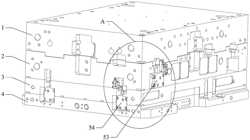
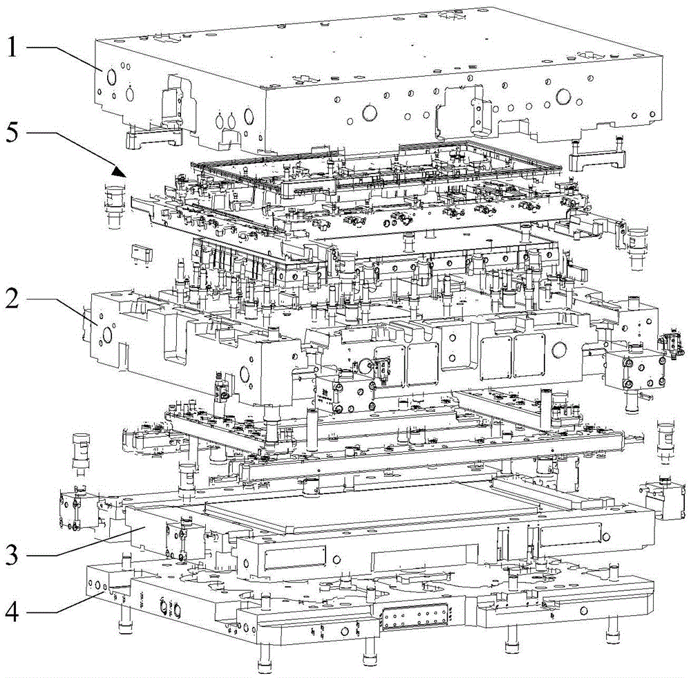
[0029] The invention provides an injection mold, see figure 1 with figure 2 , in one embodiment, the injection mold includes a fixed template 1, a movable template 2, a hot runner plate 3 and a lower template 4, such as figure 1 As shown, the fixed template 1, the movable template 2, the hot runner plate 3 and the lower template 4 are stacked together sequentially from top to bottom. It can be understood that the injection mold provided by the present invention also includes other parts to meet the requirements of the production of specific plastic products, such as fixed mold fixed plate, movable mold fixed plate, core, etc., and these parts have been used for this purpose It is well known to those skilled in the art, so details are not repeated here. For some plastic parts with relatively special structures, in ...


PUM


Abstract

The invention discloses an injection mold which comprises a fixed template, a movable template and a secondary ejection mechanism, wherein the secondary ejection mechanism comprises a push block component, an ejector plate component, a primary ejection driving device and a secondary ejection driving device; the push block component and the ejector plate component are respectively arranged on two opposite sides of the movable template and are respectively in a hollow frame structure; multiple ejection pieces are arranged on the ejector plate component; the ejection pieces penetrate through the movable template and are movably inserted into the push block component; a guide linkage mechanism which drives the push block component and the ejector plate component to be linked is arranged between the push block component and the ejector plate component; the primary ejection driving device is in driving connection with the push block component; the secondary ejection driving device is in the driving connection with the ejector plate component. Therefore, the structure of a secondary ejection mechanism is greatly simplified, and the weight of the secondary ejection mechanism is reduced, so that the secondary ejection mechanism is stable and durable, the product quality and the production efficiency are improved, and the manufacturing cost of the injection mold is reduced.

Description

technical field [0001] The invention relates to the technical field of injection molds, in particular to an injection mold with a secondary ejection mechanism. Background technique [0002] The secondary ejection mechanism of an injection mold usually includes an ejector plate and an ejector base plate. The ejector plate and the ejector base plate are respectively integrally processed from solid metal plates. The weight of the ejector plate and the ejector base account for the total weight of the entire secondary ejection mechanism the vast majority. Therefore, in the process of injection mold opening and ejection, the secondary ejection mechanism needs to overcome huge resistance, especially some large parts (for example, flat panel TV frame) need to use pusher plate when demolding, this kind of The ejection structure once again increases the load of the secondary ejection mechanism, which is likely to cause difficulty in demoulding and jamming in the actual production pro...

Claims


Application Information

Patent Timeline
Patent Type & Authority Patents(China)
IPC IPC(8): B29C45/26B29C45/40
CPCB29C45/4005B29C45/401
Inventor 袁建忠张松平王国强李兵
Owner SHENZHEN SKYWORTH PRECISION TECH
Why Eureka
Try Eureka