Return pressure rise protective valve of emergency pump source oil tank in hydraulic braking system

A hydraulic braking and emergency pump technology, applied in the hydraulic field, can solve the problems of oil tank damage, oil tank return pressure damage, system failure, etc., and achieve the effect of compact structure and reliable operation.

Active Publication Date: 2014-05-14
CHINA NORTH VEHICLE RES INST
View PDF6 Cites 0 Cited by
  • Summary
  • Abstract
  • Description
  • Claims
  • Application Information

AI Technical Summary

Problems solved by technology

[0002] The vehicle hydraulic system is the same as the general hydraulic system. It is usually composed of fuel tanks, oil pumps, valves, pipelines, etc., but due to space constraints, it often requires a compact structure. Some backup or emergency oil sources often only use closed fuel tanks, while closed fuel tanks It is necessary to consider the oil return pressure of the system. Once the oil return pressure exceeds the pressure bearing capacity of the closed oil tank, it will cause damage to the oil tank and system failure. For example, the hydraulic brake system of some special vehicles is supplied with oil from the transmission assembly. When the transmission assembly is hoisted, it is necessary to disconnect the oil supply and return oil of the brake hydraulic system from the brake supply and return oil of the transmission assembly through the quick connector (automatically sealed after disconnection)
After disconnection, the other on-board parts of the hydraulic brake system form a closed system, but the brake hydraulic system also includes a brake accumulator, which stores brake pressure oil, and the pressure oil of the accumulator passes through the system The gap of the valve (the brake valve usually adopts a slide valve) gradually enters the oil return line, causing the pressure of the oil return to rise. It will cause damage to the fuel tank due to excessive oil return pressure

Method used


Image

  • Return pressure rise protective valve of emergency pump source oil tank in hydraulic braking system
  • Return pressure rise protective valve of emergency pump source oil tank in hydraulic braking system
  • Return pressure rise protective valve of emergency pump source oil tank in hydraulic braking system

Examples


Embodiment Construction

[0020] In order to make the purpose, content and advantages of the present invention clearer, the specific implementation manners of the present invention will be further described in detail below in conjunction with the accompanying drawings and embodiments.

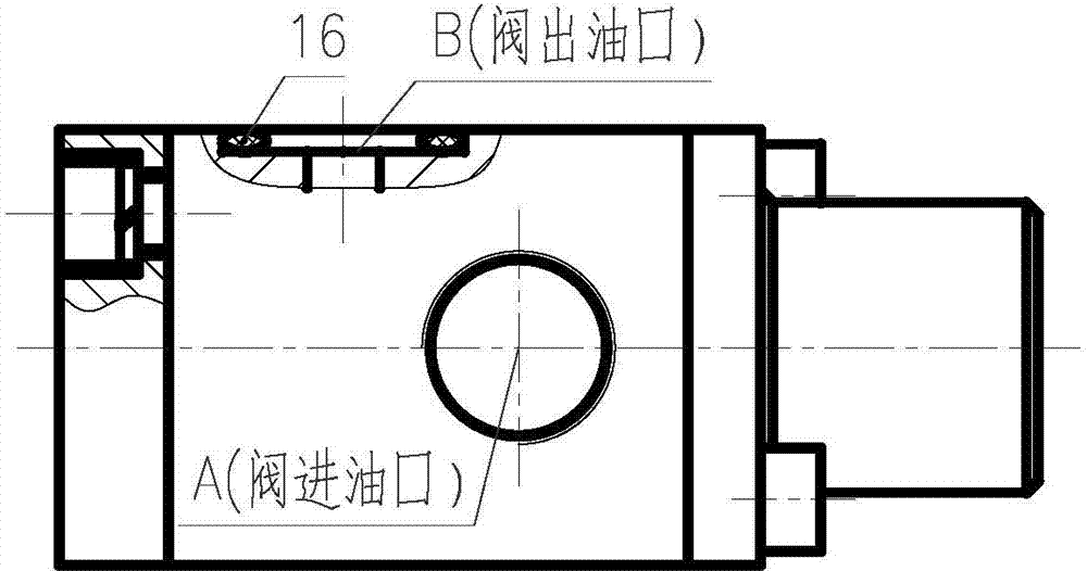
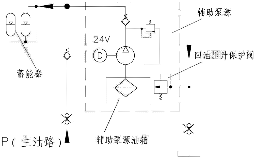
[0021] The oil return protection valve of the present invention is used as a part of the emergency pump source of the vehicle brake hydraulic system, the oil inlet is connected with the total oil return of the vehicle brake hydraulic system, and the oil outlet is connected with the oil tank of the emergency pump source.

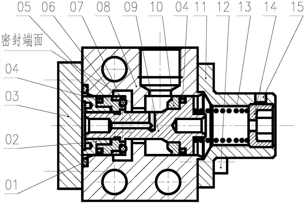
[0022] Such as figure 1 , 2 , 3, 4 and 5, the hydraulic brake emergency pump source oil tank return oil pressure rise protection valve provided by the present invention includes an O-ring 1, a nut 2, a cover plate 3, a left spool 5, and an O-ring pressure ring 6. Valve body 8, valve core 9, retaining ring 10, flange 11, screw 12, spring 13 and pressure regulating coil 14, the retaining ring 10 is inst...


PUM


Abstract

The invention belongs to the field of hydraulic technology and provides a return pressure rise protective valve of an emergency pump source oil tank in a hydraulic braking system. The return pressure rise protective valve aims at preventing the closed oil tank of an emergency pump source from being damaged by return pressure rise. The end face of a spool land is provided with a structure of an O-shaped ring. When the return pressure of the system is increased to a certain degree, the end face of the O-shaped ring of a valve element is attached to and pressed by the corresponding sealing end face of a valve body, so that an oil way is cut off and sealed in the axial direction without seepage. Through the structure of a gland ring for a hole of the valve element, the oil way is cut off and the valve element is radially sealed without seepage, so that after the return pressure is increased, the oil tank is completely disconnected with return oil, and the oil tank is protected against influence by return pressure rise. The return pressure rise protective valve of the emergency pump source oil tank in the hydraulic braking system is compact in structure, reliable in work, simple and practical.

Description

technical field [0001] The patent belongs to the field of hydraulic technology, and in particular relates to a hydraulic brake system emergency pump source oil tank return oil pressure rise protection valve, which prevents the closed oil tank of the emergency pump source from being damaged due to the increase of oil return pressure. Background technique [0002] The vehicle hydraulic system is the same as the general hydraulic system. It is usually composed of fuel tanks, oil pumps, valves, pipelines, etc., but due to space constraints, it often requires a compact structure. Some backup or emergency oil sources often only use closed fuel tanks, while closed fuel tanks It is necessary to consider the oil return pressure of the system. Once the oil return pressure exceeds the pressure bearing capacity of the closed oil tank, it will cause damage to the oil tank and system failure. For example, the hydraulic brake system of some special vehicles is supplied with oil from the tra...

Claims


Application Information

Patent Timeline
Patent Type & Authority Applications(China)
IPC IPC(8): B60T15/00
Inventor 毛福合黄开炜顾宏弢李娟韩颜莹
Owner CHINA NORTH VEHICLE RES INST
Why Eureka
Try Eureka