
Surface treating apparatus, tank body and squirting device

A technology of surface treatment device and tank, which is applied in the direction of printed circuit liquid treatment, plating tank, liquid chemical plating, etc., which can solve problems such as large-scale, inability to process the surface and back of the workpiece, and inability to obtain the quality of the coating

Active Publication Date: 2014-05-14
C UYEMURA & CO LTD
View PDF9 Cites 18 Cited by
  • Summary
  • Abstract
  • Description
  • Claims
  • Application Information

AI Technical Summary

Problems solved by technology

[0010] (i) However, in Figure 19 In the technology of the patent document 1 shown, since the elevating mechanism for immersing the frame is required, the equipment for electroless plating is complicated and enlarged. In the electroless plating treatment solution Q, there is a problem that a large amount of treatment solution is required
[0011] (ii) When the technology of Patent Document 2 is applied to electroless plating, there is a concern that the treatment liquid Q flows along the side walls W1 and W2 in the tank V, and the desired plating quality cannot be obtained.
In addition, there is a problem that a large amount of electrolyte solution is required
[0012] In addition, in Figure 20 In the technology of the patent document 2 shown, since the processing liquid is sprayed from the processing liquid nozzles 53L, 53R (Patent Document 2 figure 1 ) is sprayed downward relative to the horizontal surface, therefore, the flow velocity of the treatment liquid increases until it hits the workpiece due to the influence of gravity, and the incident angle relative to the plate-shaped workpiece 10 also becomes larger
Therefore, when the treatment liquid collides with the workpiece, foam is generated and air is entrained in the treatment liquid. As a result, the amount of dissolved oxygen in the treatment liquid increases and the quality of the surface treatment deteriorates.
Also, there is the possibility of the workpiece bending or colliding with surroundings
[0013] (iii) The technique of Patent Document 3 is a technique for coating only one side (lower surface) of a workpiece conveyed in a horizontal state, and cannot coat the surface of a workpiece conveyed in a vertical direction. and back plating
In addition, since a large amount of processing liquid Q needs to be sprayed upward on the lower surface of the workpiece, it cannot be used for thin workpieces.

Method used


Image

  • Surface treating apparatus, tank body and squirting device
  • Surface treating apparatus, tank body and squirting device
  • Surface treating apparatus, tank body and squirting device

Examples


Embodiment Construction

[0091] 1. Structure of surface treatment device 300

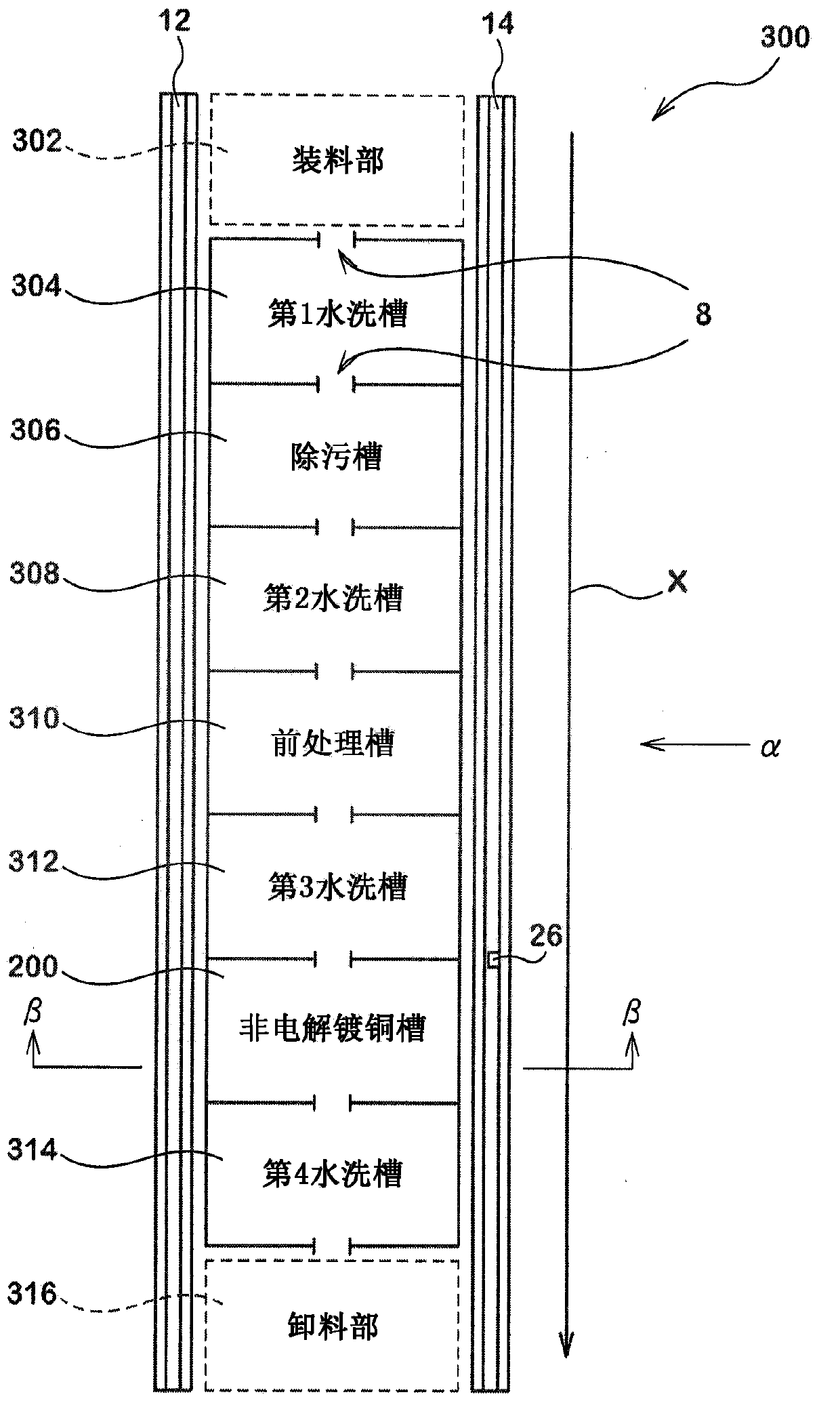
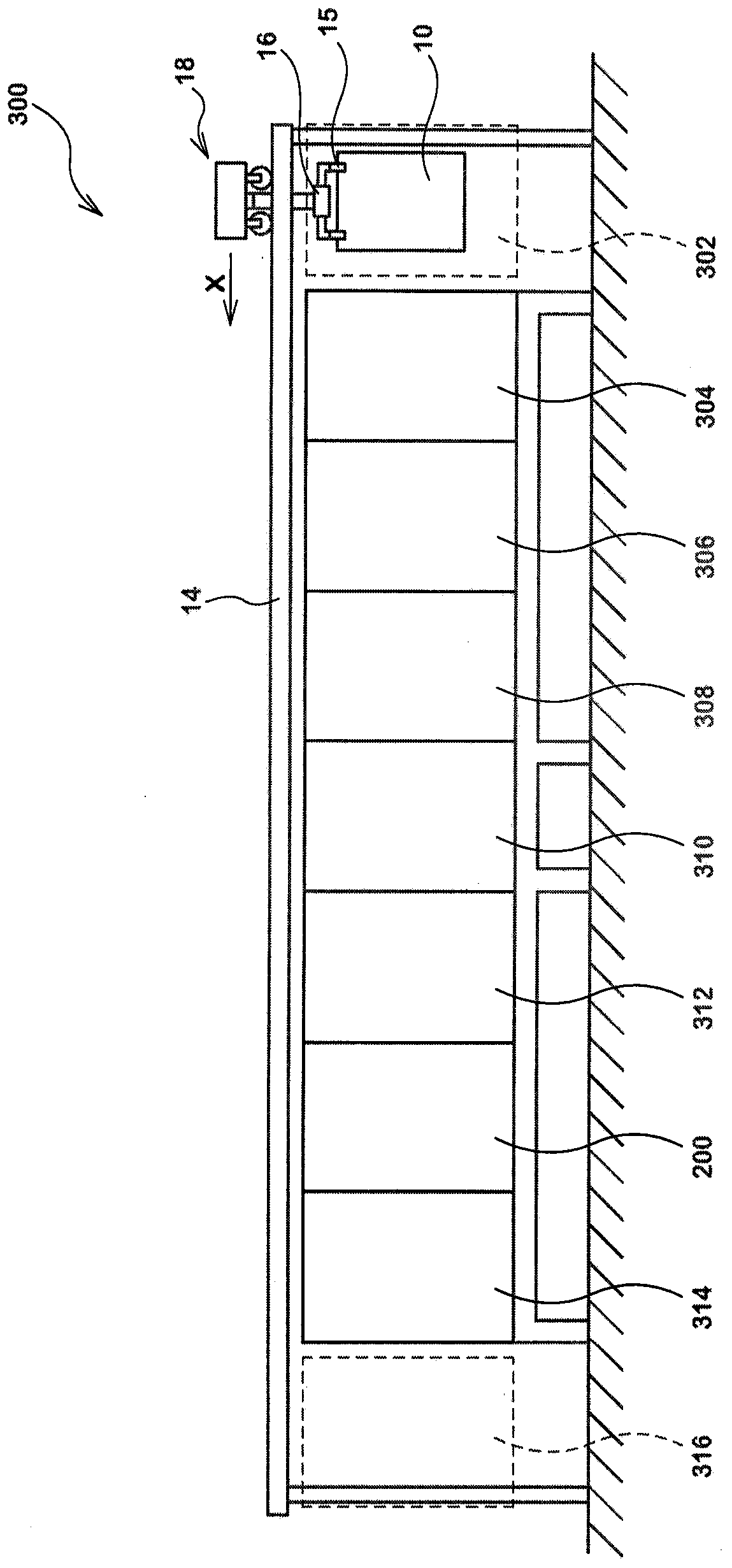
[0092] First, use figure 1 and figure 2 The structure of the surface treatment apparatus 300 of this invention is demonstrated. and, figure 1 It is a configuration diagram of the surface treatment apparatus 300 viewed from above. figure 2 is viewed from the direction of α figure 1 A side view of the surface treatment device 300 is shown. and, in figure 1 in, omitted figure 2 A transport hanger 16 and a transport mechanism 18 are shown.

[0093] Such as figure 1 As shown, in the surface treatment device 300, along the plate-shaped workpiece 10 ( figure 2 ) in the conveying direction X is provided with the loading part 302, the first washing tank 304, the decontamination tank 306, the second washing tank 308, the pretreatment tank 310, the third washing tank 312, the electroless copper plating tank 200, the fourth The washing tank 314 and the discharge unit 316 perform each process required for electroless ...


PUM


Abstract

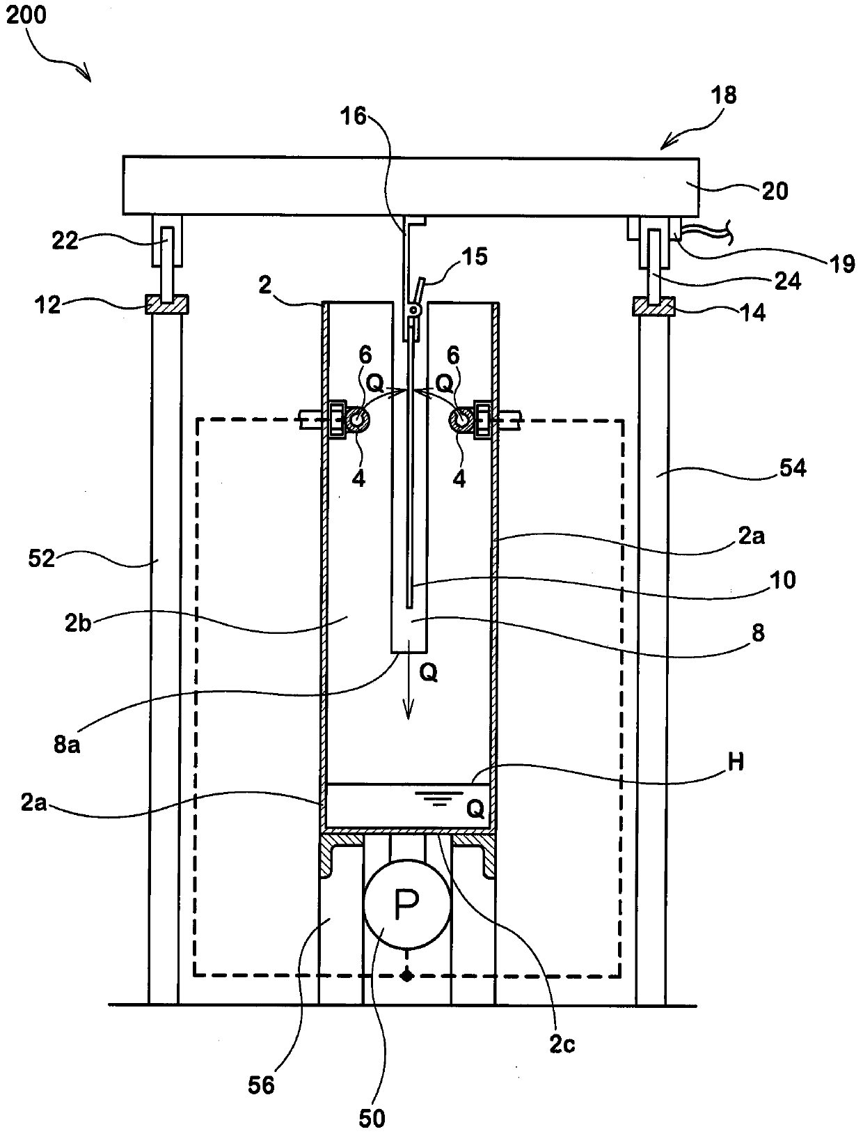
The invention provides a surface treating apparatus, a tank body and a squirting device. To perform surface treatment such as electroless plating in a high quality on a workpiece which is held vertically, a liquid squirting part (4) which has a squirt port (6) is arranged inside of each tank such as an electroless copper plating tank (200); and a processing solution (Q) is squirted from the squirt port (6) of the liquid squirting part (4) toward a plate-like workpiece (10) obliquely upward to a horizontal plane, so that the processing solution (Q) is attached to the upper side of the plate-like workpiece (10) which is clamped by a transport hanger (16) inside of the tank body (2); and the processing solution (Q) is attached to the surface of the plate-like workpiece (10) while the processing solution (Q) is running down the plate-like workpiece (10).

Description

[0001] This application incorporates the contents of the claims, specification, drawings, and abstract of Japanese Patent Application No. 2012-239795. technical field [0002] The present invention relates to surface treatment techniques such as electroless plating, decontamination treatment, pre-treatment or post-treatment, etc., for processed objects such as printed substrates. Background technique [0003] In the past, such as Figure 19 As shown, the electroless plating process is performed by immersing the plurality of plate-shaped workpieces 10 accommodated in the rack R in the process liquid Q stored in the tank (Patent Document 1). Here, the electroless plating refers to a plating method in which a layer can be plated only by immersing an object to be treated in an electrolytic solution, unlike electroplating in which current is applied. [0004] Electroless plating enables plating even on non-conductors (for example, insulating materials such as plastics and ceramic...

Claims


Application Information

Patent Timeline
Patent Type & Authority Applications(China)
IPC IPC(8): C25D17/00C25D5/08C25D17/02C23C18/00
CPCH05K3/0085H05K3/181H05K2203/1518C23C18/1619C23C18/1628
Inventor 堀田辉幸山本久光石嵜隆浩内海雅之冈町琢也星俊作浅富士夫水本纯司
Owner C UYEMURA & CO LTD
Learn More