
A double-disc hydraulic viscous speed regulating clutch

A clutch, double-plate technology, applied in the field of double-plate liquid-viscous speed-regulating clutch, can solve the problems of liquid-viscous speed-governing clutch complex structure, many control variables, inconvenient operation, etc. simple effect

Inactive Publication Date: 2016-08-31
JIANGSU UNIV
View PDF7 Cites 0 Cited by
  • Summary
  • Abstract
  • Description
  • Claims
  • Application Information

AI Technical Summary

Problems solved by technology

In the previous invention patents, the fluid-viscous speed-regulating clutch mostly adopts multi-plate type. In the test, the structure of the fluid-viscous speed-governing clutch is relatively complicated and the control variables are many, so its application has great limitations; Huang Jiahai from Zhejiang University In April 2011, on pages 106-108 of the book "Study on Fluid Shear Transmission Mechanism of Fluid Viscous Speed ​​Control Clutch", a manual adjustment type liquid viscous speed control clutch was disclosed, relying on the lock nut on the input shaft and the fixed Screws are used to manually adjust the distance between the active and passive plates. Every time the distance between the active and passive plates is adjusted, the cabinet must be disassembled. After the adjustment is completed, the cabinet must be installed again, which has the disadvantages of inconvenient operation, time-consuming and laborious, etc.

Method used


Image

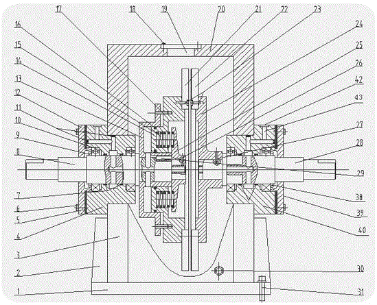
  • A double-disc hydraulic viscous speed regulating clutch
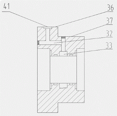
  • A double-disc hydraulic viscous speed regulating clutch
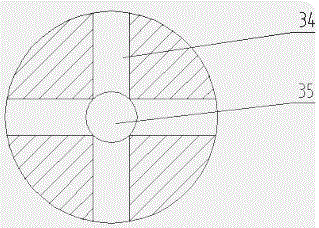
  • A double-disc hydraulic viscous speed regulating clutch

Examples


Embodiment Construction

[0014] The present invention will be further described in detail below in conjunction with the drawings.

[0015] The structure of a double-plate liquid viscous speed-regulating clutch of the present invention is as follows Figure 1 to Figure 3 As shown, it includes the bottom plate 1, the rib plate 2, the lower box cover 3, the first transparent cover 4, the dustproof sealing washer 5, the bearing end cover fixing screw 6, the O-ring sealing washer 7, the input shaft 8, the lock nut 9, The first ball roller ball bearing 10, the plug 11, the first bearing end cover 12, the oil cylinder 13, the piston 14, the return spring 15, the sealing gasket 16, the drive pin 17, the through hole cover fixing screw 18, the perspective hole 19 , Upper box cover 20, active plate 21, passive plate 22, friction plate fixing screw 23, passive plate support 24, spring stop 25, set screw 26, support fixing screw 27, output shaft 28, ordinary flat key 29 , Oil drain hole 30, fixing screw 31, first o...


PUM


Abstract

A double-piece hydro-viscous speed adjusting clutch comprises an input device, an output device and a box body, wherein the box body comprises an upper box cover and a lower box cover, and the upper box cover and the lower box cover are connected through fixing screws on a flange; the input device comprises an input shaft and a first transparent cover, the first transparent cover is fixed to the wall face of the upper box cover and the wall face of the lower box cover, the input shaft is located in the first transparent cover, the portion, located at the shaft end of an inner cavity of the box body, of the input shaft is respectively provided with an oil cylinder, a piston, a driving piece and a spring stopping base, and an oil conveying hole is formed in the input shaft; the output shaft comprises an output shaft and a second transparent cover, the output shaft is located in the second transparent cover, the portion, located at the shaft end, of the inner cavity of the box body is respectively provided with a driven piece and a driven piece support base, and an oil conveying hole is formed in the output shaft. Compared with a traditional hydro-viscous speed adjusting clutch, the double-piece hydro-viscous speed adjusting clutch has the advantages of being simple in structure, safe, reliable, convenient and easy to control, easy to detect and control automatically and the like.

Description

Technical field [0001] The invention relates to a liquid viscosity speed-regulating clutch, in particular to a double-plate liquid viscosity speed-regulating clutch. Background technique [0002] With the continuous development of society, energy saving and consumption reduction has become one of the major themes in the world today. In industrial and agricultural production, the introduction of liquid-viscous speed-regulating clutches in mechanical equipment for speed regulation and flexible starting has the potential to achieve significant energy-saving effects, and therefore has attracted extensive attention from experts at home and abroad. [0003] Liquid viscous transmission is a new type of fluid transmission that uses liquid viscosity or shear force to transmit power, referred to as liquid viscous transmission. The liquid viscous transmission technology is applied to the speed control clutch. The liquid viscous speed control clutch is developed. The liquid viscous speed cont...

Claims


Application Information

Patent Timeline
Patent Type & Authority Patents(China)
IPC IPC(8): F16D35/00
Inventor 谢方伟张先俊崔建中王存堂宣芮盛刚
Owner JIANGSU UNIV
Learn More