
High-impact piezoelectric accelerometer

An accelerometer and piezoelectric technology, applied in the field of high-impact piezoelectric accelerometers, can solve the problems of velocity and displacement shock spectrum velocity, unreasonable displacement, spurious drift of output baseline, etc., to reduce strain and reduce zero The effect of drifting and reducing the effective strain

Active Publication Date: 2014-05-14
YMC PIEZOTRONICS
View PDF5 Cites 4 Cited by
  • Summary
  • Abstract
  • Description
  • Claims
  • Application Information

AI Technical Summary

Problems solved by technology

Zero drift is an error often encountered in the shock measurement of high-impact piezoelectric accelerometers. It is manifested as a spurious drift of the output baseline after a high-g impact. The most direct consequence of the "zero drift" phenomenon is that the acceleration The velocities and displacements obtained by signal integration reach unacceptable orders of magnitude. The velocity and displacement of the calculated shock spectrum in the low frequency band are obviously unreasonable

Method used


Image

  • High-impact piezoelectric accelerometer
  • High-impact piezoelectric accelerometer

Examples


Embodiment Construction

[0014] Below in conjunction with accompanying drawing and specific embodiment, further illustrate the present invention, it should be understood that these embodiments are only used to illustrate the present invention and are not intended to limit the scope of the present invention, after reading the present invention, those skilled in the art will understand various aspects of the present invention Modifications in equivalent forms all fall within the scope defined by the appended claims of this application.

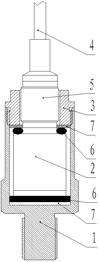
[0015] Such as figure 1 The shown high-impact piezoelectric accelerometer includes a hollow mounting seat 1, and a core body 2 is arranged in the hollow mounting seat, and the core body is pressed into the mounting seat by a compression ring 3, and the cable 4 is connected to the core body through the plug 5, and shock-absorbing pads 6 and insulating pads 7 are arranged between both ends of the core body, the compression ring and the mounting seat. Both ends of the cor...


PUM


Abstract

The invention discloses a high-impact piezoelectric accelerometer. The high-impact piezoelectric accelerometer comprises a hollow installing seat, a core is arranged in the hollow installing seat through a compressing ring in a press fit mode and is connected with a cable through a plug, one shock insulation cushion and one insulating cushion are arranged between one end of the core and the compressing ring, and another shock insulation cushion and another insulating cushion are arranged between the other end of the core and the installing seat. Because the shock insulation cushions large in damping are installed at the two ends of the core of the piezoelectric accelerometer, high-frequency large-amplitude acceleration generated by strong-impact waves on a structure can be filtered out, and transverse acceleration transmitted to an acceleration sensor can be reduced so as to achieve the purpose of reducing zero drift. Due to the adoption of a base strain isolation type structure, strain of sensitive elements can be effectively reduced; because the insulating cushions are arranged at the two ends of the core and serve as isolators, the accelerometer can be isolated from an installing face mechanically so that effective strain transmitted to the accelerometer can be reduced and the purpose of reducing zero drift can be achieved.

Description

technical field [0001] The patent of the present invention relates to a piezoelectric accelerometer technology, in particular to a high-impact piezoelectric accelerometer. Background technique [0002] Piezoelectric acceleration sensors are also called piezoelectric accelerometers. It is an inertial sensor. It uses the piezoelectric effect of certain materials such as quartz crystals. When the accelerometer is vibrated, the force exerted by the mass on the piezoelectric element also changes. When the measured vibration frequency is much lower than the natural frequency of the accelerometer, the force change is proportional to the measured acceleration. Zero drift is an error often encountered in the impact measurement of high-impact piezoelectric accelerometers. It is manifested as a spurious drift of the output baseline after a high-g impact. The most direct consequence of the "zero drift" phenomenon is that the acceleration The velocities and displacements obtained by s...

Claims


Application Information

Patent Timeline
IPC IPC(8): G01P15/09
Inventor 陈启山吴芳
Owner YMC PIEZOTRONICS
Learn More