
Offset Cancellation Circuit

A technology of offset elimination and offset voltage, which is applied in the direction of adjusting electrical variables, DC level changes, instruments, etc., can solve problems such as application, and achieve the effect of eliminating offset voltage

Inactive Publication Date: 2016-03-23
YAMAHA CORP
View PDF6 Cites 0 Cited by
  • Summary
  • Abstract
  • Description
  • Claims
  • Application Information

AI Technical Summary

Problems solved by technology

Therefore, the related offset cancellation circuit 95 has a problem in that it is difficult to sufficiently generate a voltage drop corresponding to the dispersion of resistance in the bridge circuit in an arbitrary temperature range, and can cancel the offset voltage Voff only at a specific temperature
[0006] This problem is not limited to the magnetic sensor 90 configured by bridging a plurality of GMR elements 91 to 94, but this problem is also applied to a bridged resistance type sensor in which a plurality of resistance elements are bridged.

Method used


Image

  • Offset Cancellation Circuit
  • Offset Cancellation Circuit
  • Offset Cancellation Circuit

Examples


Embodiment Construction

[0020] Preferred embodiments of the present disclosure will be described in detail below with reference to the accompanying drawings. Components common to the embodiments described below are denoted by the same reference numerals, and repeated description thereof will be omitted.

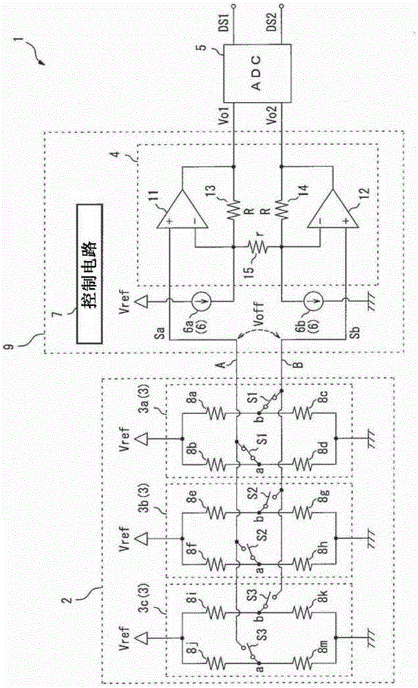
[0021] figure 1 is a circuit diagram showing the configuration of the sensor circuit 1 including the offset cancellation circuit 9 of the present disclosure. The sensor circuit 1 includes a sensor section 2 , an offset cancellation circuit 9 , and an AD (Analog / Digital) converter 5 .

[0022] The sensor section 2 includes three magnetic sensors 3a, 3b, 3c for sensing external magnetic fields in three directions orthogonal to each other, and is configured such that the magnetic sensors 3a, 3b, 3c sense external magnetic fields in different directions, respectively. magnetic field. The sensor section 2 sequentially switches the three magnetic sensors 3a, 3b, 3c into the measurement mode one by one...


PUM


Abstract

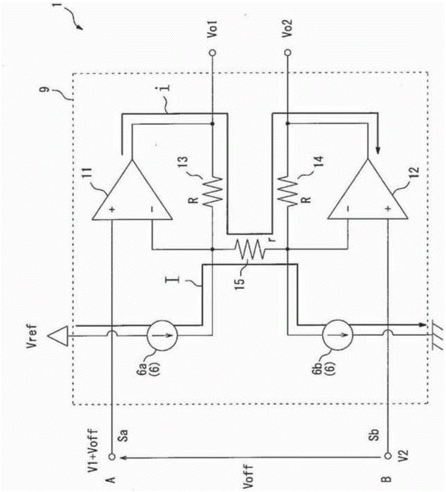
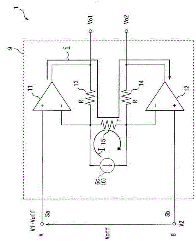
An offset cancel circuit includes a first amplifying section, a second amplifying section, a third resistor connected between a non-inverting input terminal of the first amplifying section and a non-inverting input terminal of the second amplifying section, and a current source. In the offset cancel circuit, the current source causes a constant current to flow through the third resistor to cancel an offset voltage from output signals of first and second amplifying sections, the constant current corresponding to the offset voltage contained in first and second output signals output from a bridge resistance type sensor.

Description

technical field [0001] The present disclosure relates to an offset cancellation circuit capable of canceling an offset voltage contained in an output signal of a bridged resistance type sensor configured by connecting a plurality of resistance elements by bridges. Background technique [0002] In general, a magnetic sensor in which a plurality of GMR elements (giant magnetoresistance effect elements) are bridged (for example, JP-A-2007-212275) is known. In the GMR element, according to an external magnetic field, the magnetization direction of the free layer is relatively rotated with respect to the fixed magnetization direction of the pinned layer, so that the resistance is changed. When focusing on the electrical characteristics of the GMR element, the GMR element is a type of resistive element. Therefore, in the case where a plurality of GMR elements constitute a bridge circuit, it is possible to sense an external magnetic field through a change in the potential balance ...

Claims


Application Information

Patent Timeline
Patent Type & Authority Patents(China)
IPC IPC(8): G05F1/56
CPCH03K5/003
Inventor 宫崎雅人前岛利夫
Owner YAMAHA CORP
Learn More