[0030] Implementation
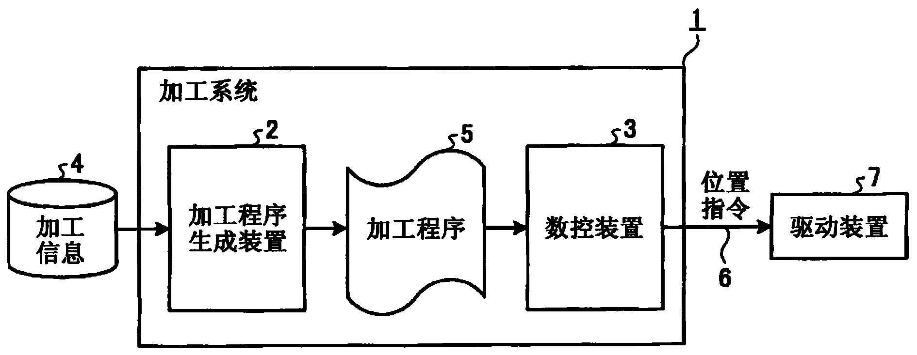
[0031]figure 1 It is a block diagram showing the schematic configuration of the processing system in this embodiment. In the figure, 1 is a machining system, which has a machining program generation device 2 and a numerical control device (NC) 3 . The machining program creation device 2 creates a machining program 5 based on machining information 4 input from the outside. The numerical control device 3 generates a position command 6 of the machine tool (not shown) at each time based on the machining program 5 , and inputs the position command 6 to a driving device (servo control device) 7 of the machine tool to move each axis of the machine tool. , for the desired processing. Here, processing information 4 refers to material (shape and material of material, etc.), product shape, tool used (shape, material, etc.), processing method, processing pattern (pattern), processing conditions, and required precision. A set of information required to determine the action of the machine during processing.
[0032] figure 2 yes means figure 1 A block diagram of the detailed structure of the machining program generating device 2 in FIG. In the figure, 21 is a movement command generating unit, 22 is an acceleration/deceleration command generation unit, 23 is a superposition command unit, 24 is a mechanical dynamic characteristic, 25 is a movement command, 26 is an acceleration/deceleration command, and 27 is a superposition command. The movement command generation unit 21 and the acceleration/deceleration command generation unit 22 respectively instruct the machining program 5 with a movement command 25 and an acceleration/deceleration command 26 , and preferably also instruct the machining program 5 with a superposition command 27 through the superposition command unit 23 . The movement command generator 21 calculates the movement of the tool relative to the material (workpiece) for machining a desired product shape based on the machining information 4 , and instructs the movement as a movement command 25 to the machining program. Here, the movement command 25 is a command for moving the tool, and includes at least a command path and a command speed. The acceleration/deceleration command generator 22 obtains the acceleration/deceleration command 26 with the shortest machining time based on the movement command 25 and the mechanical dynamic characteristics 24 , and instructs the machining program 5 .
[0033] Here, the mechanical dynamic characteristics 24 are limited so that the generated acceleration and deceleration commands 26 are data within the range in which each axis of the machine can operate (can be output). The mechanical dynamic characteristic 24 is, for example, a constraint condition (each having an upper limit value and a lower limit value) (D) that is greater than or equal to at least one of any one of speed, acceleration, torque, and current. Furthermore, the machine dynamic characteristics 24 may include any relationship of responses, including the relationship of actual machine position, velocity, acceleration, current, and torque responses to position commands of each axis of the machine tool. This relationship is expressed, for example, in the form of a transfer function (frequency response) or a motion equation. In addition, this relationship may not be the relationship between the actual machine position, speed, acceleration, current, and torque relative to the position command, but may be represented by, for example, the relationship between the actual machine position, speed, acceleration, current, and torque relative to the speed command or acceleration command. Position, speed, and acceleration can be converted by differentiation and integration. Similarly, the position can be obtained by integrating the acceleration command, current command, torque command, and speed command. Therefore, the conversion is easy and can be handled in the same way.
[0034] In addition, the acceleration and deceleration instruction 26 is an instruction for controlling the acceleration and deceleration processing in the numerical control device 3 by the processing program, and specifically refers to the acceleration, deceleration, and the end point of the command path (the connection between the command path and the next command path). ) and the acceleration/deceleration pattern (linear acceleration/deceleration or S-shaped acceleration/deceleration, etc.).
[0035] and, in figure 2 Among them, the overlapping command unit 23 may obtain the overlapping command 27 from the movement command 25 , the acceleration/deceleration command 26 and the required accuracy (included in the machining information 4 ), and instruct it to the machining program 5 . Here, the overlapping command 27 refers to specifying the distance or time to perform superimposition for the movement commands 25 that are usually executed in the order indicated to the machining program 5, so that the next movement command 25 can be started before the completion of a certain movement command 25. One movement instruction 25, so that multiple movement instructions 25 are executed overlappingly. By performing this superposition, the machining time of the machining program 5 composed of a plurality of movement commands 25 can be shortened.
[0036] under, image 3 yes means figure 1 A block diagram of the detailed structure of the numerical control device 3 in . In the figure, 31 is an acceleration/deceleration determination unit, 32 is a position command generation unit, 33 is an actual mechanical dynamic characteristic, 34 is an acceleration/deceleration data, 35 is an adjustment coefficient, and 36 is a load. The other constituent elements are as described above, and description thereof will be omitted.
[0037] Here, the actual mechanical dynamic characteristics 33 are data similar to the mechanical dynamic characteristics 24, but the mechanical dynamic characteristics 24 are stored in the processing program generation device 2, and are the nominal dynamic characteristics of the machine (the nominal dynamic characteristics assumed in a standardized manner). value), on the other hand, the actual mechanical dynamic characteristic 33 is stored in the numerical control device 3 and can reflect the adjustment coefficient ( Adjustment signal or adjustment parameter) 35 , and mechanical load 36 (loaded weight, inertia, motor current, motor temperature, etc.) obtained from the drive device 7 or a sensor not shown to change the dynamic characteristics. By configuring as described above, it is possible to set the mechanical dynamic characteristics more in line with the actual machine.
[0038] The acceleration/deceleration determination unit 31 converts and calculates the acceleration/deceleration data 34 satisfying the constraints of the actual mechanical dynamic characteristics 33 when the movement command 25 and the acceleration/deceleration command 26 are given. Here, the acceleration/deceleration data 34 is data for controlling acceleration/deceleration by the position command generator 32 .
[0039] The position command generation unit 32 performs acceleration, deceleration and interpolation based on the movement command 25 and the acceleration/deceleration data 34 to generate the position command 6 .
[0040] In addition, when the superposition command 27 is instructed to the machining program 5, the acceleration/deceleration judging unit 31 also judges whether or not the superposition command 27 instructed can be executed, and the superposition command 27 as a judgment result is included in the acceleration/deceleration data 34. . When the overlapping command 27 is included in the acceleration/deceleration data 34 , the position command generator 32 starts the next movement command according to the overlapping command 27 .
[0041] Figure 4 It is a figure which shows the flow chart explaining the schematic operation|movement of the processing system of this embodiment. In the drawing, a machining program 5 is generated in STEP 11 based on machining information 4 input from the outside. In STEP 12, the position command 6 of the machine tool (not shown) is generated at each time according to the processing program created in STEP 11, and the machine tool is operated by inputting the position command 6 to the drive device (servo control device) 7 , for the desired processing.
[0042] Figure 5 yes yes Figure 4 The figure of the flow chart explaining the detailed operation of STEP11. In the drawing, in STEP 21 , a movement command 25 is generated based on machining information input from the outside. An acceleration/deceleration command 26 is generated in STEP 22 . A coincidence command 27 is generated in STEP23. In STEP 21, based on the machining information 4, the movement command generation unit 21 calculates the movement of the tool relative to the material (workpiece) for machining a desired product shape, and sends the movement command 25 to the machining program 5 as a movement command 25 for each block. instruct. In STEP 22 , the acceleration/deceleration command generator 22 finds the acceleration/deceleration command 26 with the shortest machining time based on the movement command 25 of each block and the mechanical dynamic characteristics 24 , and instructs the machining program 5 . In STEP 23 , the superposition command unit 23 obtains the superposition command 27 from the movement command 25 , the acceleration/deceleration command 26 , and the required accuracy (included in the machining information 4 ), and instructs the machining program 5 .
[0043] Image 6 yes yes Figure 4 The figure of the flow chart explaining the detailed operation of STEP12. In the figure, in STEP 31 , when given the movement command 25 and the acceleration/deceleration command 26 , the acceleration/deceleration determination unit 31 converts them and calculates acceleration/deceleration data 34 satisfying the constraints of the actual mechanical dynamic characteristics 33 . If the acceleration and deceleration command 26 can be executed (the constraint condition of the actual mechanical dynamic characteristic 33 is satisfied), the acceleration and deceleration data 34 is consistent with the acceleration and deceleration command 26; if it cannot be executed (the constraint condition of the actual mechanical dynamic characteristic 33 is not met), the A preset value (default value of the acceleration/deceleration data set by a parameter or the like) is used as the acceleration/deceleration data 34 . Similarly, whether or not the coincidence command 27 can be executed is also judged. That is, when the superposition command 27 is instructed to the machining program 5, the acceleration/deceleration judging unit 31 also judges whether or not the given superposition command 27 can be executed, and when the operation is performed according to the superposition command 27, the constraints of the actual mechanical dynamic characteristics 33 are satisfied. In the case of conditions, the coincidence command 27 is also included in the acceleration and deceleration data 34 to indicate, otherwise, in the case of not satisfying the constraint conditions, the indicated coincidence command 27 is not used, but the preset value ( The default value of the overlap amount set by parameters, etc.) or 0 (non-overlap) is included in the acceleration/deceleration data as the overlap command 27.
[0044] In STEP 32 , the position command generator 32 performs acceleration/deceleration and interpolation based on the movement command 25 and the acceleration/deceleration data 34 to generate the position command 6 . The interpolation method follows the instruction path indicated by the movement instruction 25 . For example, linear interpolation, circular interpolation, spline interpolation, etc. are performed according to the type of path. When the superposition command 27 is included in the acceleration/deceleration data 34 , the position command generator 32 starts the next movement command according to the superposition command 27 .
[0045] Figure 7 An example of machining program 5 is shown in . The command group indicated by each row refers to the movement command of each block (in this example, 4 blocks). N is the sequence number, G1 is the linear interpolation, X, Y are the coordinate values of the X-axis and Y-axis respectively, A is the acceleration, D is the deceleration, C is the coincidence amount, V is the deceleration speed at the end point of the program block, F is the feed rate. Here, the G command, the coordinate value X, Y, and F commands are command groups constituting the movement command. The present embodiment is characterized in that an acceleration/deceleration command (A command, D command, V command) and a C command for specifying an overlapping amount are instructed in the same block as the movement command.
[0046] In this example, as shown above, each program block is a part described on one line, usually starting with a sequential number and ending with a block terminator ( Figure 7 and Figure 8 The part of the area ending in ) is a program block. Generally, the processing program of the numerical control device is processed according to the operation sequence of the program called an interpreter. Basically, after one block is read and processed, the next block is read (for interpolation purposes, sometimes Several program blocks are also read). In addition, even if there is a numerical control device different from this embodiment that does not use the term "program block", if there is a unit including one movement command (command group) that is read and processed at once, it means The unit (area).
[0047] For example, in the N1 program block, move to the X10 and Y0 positions at a feed rate of 3000, the acceleration at this time is 300, the deceleration is 600, the overlap with the next movement (N2 program block) is 0.5, and the end of the program block The deceleration speed at is 1000. Here, the constraints of the actual mechanical dynamics are, for example:
[0048] The maximum acceleration of the X axis (acceleration allowable value): 1200
[0049] The maximum acceleration of the Y axis (acceleration allowable value): 600
[0050] X-axis maximum acceleration (deceleration allowable value): 600
[0051] The maximum acceleration of the Y axis (deceleration allowable value): 600.
[0052] In this case, in Figure 7 In the processing program of , since the acceleration and deceleration indicated by A and D are within the allowable range, it is judged that it can be executed, and the operation is performed according to the processing program.
[0053] in addition, Figure 8 The second example of machining program 5 is shown. compared to Figure 7, the value of A in N1 block, the value of D in N2, and the value of C in N3 are different. In this case, if the constraint conditions of the actual mechanical dynamic characteristics become the above values, then the Figure 8 In the machining program, the value of the acceleration command 1800 indicated by A of the N1 block has exceeded the acceleration allowable value of the X axis, so it is judged that it cannot be executed, and the acceleration command is changed to the default value (for example, the acceleration allowable value is 1200) , program block N1 program block moves with an acceleration of 1200. Similarly, in the N2 block, since the deceleration command ( 900 ) exceeds the Y-axis deceleration allowable value, it is also changed to the Y-axis deceleration allowable value 600 as the allowable value, and operates.
[0054] In addition, at the end point of the N3 block, the value of the acceleration in the normal direction (acceleration in the direction perpendicular to the traveling direction of the path) generated at the corner when the machining program is generated is calculated so that it reaches the specified allowable value , and set the Overlap Amount to 0.15. This amount of overlap results in a smooth curved path at the corner, but if you pass the curved corner at the speed specified by the V command (800), the acceleration (in this case, at If the acceleration generated by the normal direction of the path) exceeds the allowable acceleration, the specified overlap amount of 0.15 cannot be executed, so the overlap command is not used, but is corrected to the overlap amount that makes the generated acceleration consistent with the allowable acceleration (for example, set The instruction value of the C instruction was corrected from 0.15 to 0.3).
[0055] In addition, in the present embodiment, the acceleration is not too large by correcting the overlapping amount as described above, but it is also possible to make the acceleration not too large by correcting the velocity (V command) at the end point of the block.
[0056] will follow Figure 7 or Figure 8 The trajectory in the case of the operation of the machining program is Figure 9 shown in, the velocity waveform at Figure 10 shown in . in accordance with Figure 8 When operating a machining program, the command that cannot be executed as described above is corrected, and by operating based on the corrected command, it becomes the same as Figure 7 same action.
[0057] like Figure 9 as shown, Figure 7 , Figure 8 The tool path of the machining program has a roughly square outline shape. The three corners are formed into smooth curves by the action of the coincidence command (C command). The lengths in the moving direction of the curved portion are respectively 0.3, 0.4, and 0.5 according to the overlapping command.
[0058] exist Figure 10 In , the vertical axis represents the moving speed of the tool, and the horizontal axis represents time. 4 mountain shape representations Figure 7 , Figure 8 Acceleration and deceleration when each movement command from block N1 to block N4 of the machining program is in motion. It can be seen that different acceleration and deceleration are obtained by the action of the acceleration command (A command) and the deceleration command (D command), thereby performing fine motion control.
[0059] As described above, by operating the machine tool based on the acceleration, deceleration, deceleration speed (composite speed) and overlap amount instructed to each block of the machining program, it is possible to further improve the accuracy of a specific part, or for each movement It is possible to finely change actions such as acceleration and deceleration by command, and realize flexible mechanical actions corresponding to machining.
[0060] According to the present embodiment, in particular, machining time can be shortened by finely instructing mechanical operations such as acceleration and deceleration according to machining by a machining program. In addition, it is not necessary to strictly judge whether or not to execute the program at the time of program generation, and the machining program generation does not require labor, and the machining time can be shortened.
[0061] In addition, in the above description, in the processing of STEP 31, when the constraint condition is exceeded, a warning may be issued to stop the mechanical operation. In particular, when there is a large difference between the assumed mechanical dynamic characteristics and the machining program generation time, it is preferable to stop the machine operation and regenerate the program from the viewpoint of precision management of workpieces or shortening the total time during mass production machining.
[0062] In this embodiment, the acceleration, deceleration, overlap amount, and deceleration speed at the end point of the block are indicated by the addresses of A, D, C, and V respectively, but it is not limited to this, and it can also be assigned to any unused letter.
[0063] In addition, by specifying the command realized based on the address of A, D, C, V in the comment (in the processing program, the character string of the comment is usually surrounded by parentheses and regarded as a comment), it is possible to use the commands compatible with the above commands. The same machining program is used in the NC unit and the incompatible NC unit. That is, in the numerical control device that has the function of changing the acceleration, deceleration, overlap amount, and deceleration speed at the end point of the block from the machining program, the acceleration, deceleration acceleration, deceleration, and overlap amount indicated in the comment , The deceleration speed at the end point of the block is interpreted, and control is performed corresponding to the above command (command value generation). On the other hand, in a numerical control device that is not compatible with the above-mentioned command, the above-mentioned command is not executed because it is placed in a comment, but performs the same operation as in the prior art. It is also possible to judge whether a comment contains a common comment or whether it contains acceleration, deceleration acceleration, deceleration, coincidence amount, and deceleration speed at the end of the block by whether the comment contains a specific identifier.
[0064] As described above, according to the present embodiment, the processing program generation device 2 generates movement commands for each program block, and generates acceleration and deceleration commands corresponding to each movement command based on the mechanical dynamic characteristics, and generates the same program as the movement command. The acceleration and deceleration command is indicated in the block in numerical form, and the numerical control device 3 judges the acceleration and deceleration data that can actually act based on the movement command, the acceleration and deceleration command and the actual mechanical dynamic characteristics, and performs acceleration and deceleration and interpolation based on the movement command and the acceleration and deceleration data. Therefore, it is possible to instruct flexible mechanical actions corresponding to fine machining from the machining program. In addition, it is not necessary to strictly judge whether execution can be performed at the time of program creation, which has the effect of shortening the machining time.
[0065] In addition, according to this embodiment, as a command related to acceleration and deceleration, any one of the acceleration in the tangential direction of each block, the deceleration, and the deceleration at the end point of the command path can be instructed to be greater than or equal to one, so that freedom can be realized. Acceleration and deceleration commands with high accuracy have the effect of being able to fine-tune the processing time and precision.
[0066] Moreover, according to this embodiment, as the mechanical dynamic characteristics, it includes: the constraint condition that any of the speed, acceleration, torque, and current of each axis of the machine is greater than or equal to 1; and any of the speed, acceleration, torque, and current is greater than or equal to 1 Or relative to the relational expression of the position command, in the processing program generating device 2, the acceleration and deceleration command with the shortest processing time is obtained according to the constraint conditions and the relational expression, so when generating the processing program without labor, it has the advantage of shortening the processing time. Effect.
[0067] Furthermore, according to the present embodiment, in the processing program generating device 2, based on the movement command and the acceleration/deceleration command, the trajectory accuracy and the specified value in the case where the movement command overlaps with the next movement command after that are obtained. The amount of overlap required to be consistent with the accuracy is indicated to the machining program as an overlap command. In the numerical control device 3, the overlap command is followed so that the movement command and the next movement command following it follow the direction indicated to the machining program. The method of superimposing the distance corresponding to the superposition command starts the generation of the position command of the next movement command. Therefore, the machining program can further instruct the trajectory accuracy, and has the effect of enabling better machining.
[0068] And, according to this embodiment, the actual mechanical dynamic characteristics include: the constraint condition that any of the speed, acceleration, torque, and current of each axis of the machine is greater than or equal to 1; and any of the speed, acceleration, torque, and current is greater than or equal to 1 With respect to the relational expression of the position command, in addition, the actual mechanical dynamic characteristics are constructed in such a way as to reflect the mechanical load and the adjustment coefficient set in the numerical control device 3. In the numerical control device 3, based on the movement command instructed to the machining program, the actual Dynamic characteristics, to judge whether the acceleration and deceleration command can be executed. If it can be executed, the indicated acceleration and deceleration command will be used as the acceleration and deceleration data. If it cannot be executed, the preset value will be used as the acceleration and deceleration data. The data is accelerated and decelerated according to the acceleration and deceleration data, so there is an effect that the processing time can be shortened without labor.
[0069] In addition, according to the present embodiment, the program generation device is configured to generate movement commands for each program block, and to generate acceleration and deceleration commands for each axis when moving in accordance with the movement commands based on mechanical dynamic characteristics. Therefore, manual work is not required. Instructing commands related to acceleration and deceleration for each movement command has the effect of making it easier to generate a program with a short machining time.
[0070] Furthermore, according to the present embodiment, since the program generating device is configured as above, when machining based on a machining program in which an acceleration/deceleration command and a superimposition command are instructed, the operator does not need to perform acceleration/deceleration exceeding the mechanical dynamic characteristic range every time. Confirmation of the command and overlapping command has the effect of shortening the processing time without wasting man-hours.