Control method and system for heart CT (computed tomography) and CT machine

A CT scanning and heart technology, applied in the control field of CT machine and cardiac CT scanning, can solve the problems of image quality reduction, arrhythmia, inaccurate heartbeat timing prediction, etc.

Active Publication Date: 2014-05-21
SIEMENS SHANGHAI MEDICAL EQUIP LTD
View PDF5 Cites 4 Cited by
  • Summary
  • Abstract
  • Description
  • Claims
  • Application Information

AI Technical Summary

Problems solved by technology

Some existing cardiac CT scans usually control the exposure of X-rays based on predicting the time when the heartbeat occurs. However, in practical applications, arrhythmias often occur due to patient stress or ab

Method used


Image

  • Control method and system for heart CT (computed tomography) and CT machine
  • Control method and system for heart CT (computed tomography) and CT machine
  • Control method and system for heart CT (computed tomography) and CT machine

Examples


Embodiment 1

[0038] figure 2It is an exemplary flow chart of a control method for cardiac CT scanning in Embodiment 1 of the present invention. Such as figure 2 As shown, the process mainly includes the following steps:

[0039] Step 201, determine the image scanning range of the heart.

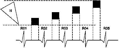
[0040] Step 202 , for each scanning segment within the image scanning range, image data acquisition within a preset scanning viewing angle range is completed within at least one cardiac rest period. Wherein, the scanning angles of view of the image data corresponding to a single scan segment in different cardiac resting periods do not overlap and equal to a preset range of scanning angles after accumulation.

[0041] Further, the method may further include: for each scan segment of the heart, reconstructing the data of the scan segment by using the collected image data within a preset scan viewing angle range.

[0042] image 3 It is an exemplary structural diagram of a control system for cardiac C...

Embodiment 2

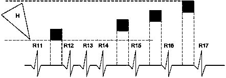
[0049] Embodiment 2: step-by-step scanning

[0050] Figure 4 It is a schematic flow chart of the control method of cardiac CT step scan in the second embodiment of the present invention. Such as Figure 4 As shown, the process mainly includes the following steps:

[0051] Step 401, determine the image scanning range of the heart.

[0052] Step 402: Move the initial scan segment of the heart into the scan area according to the image scan range.

[0053] In this step, the initial scanning segment of the heart can be moved into the scanning area by moving the patient examination table. Alternatively, in practical applications, the initial scanning segment of the heart may also be moved into the scanning area by moving the CT gantry. Alternatively, the CT gantry and patient table can be moved simultaneously to move the initial scan segment of the heart into the scan field.

[0054] Step 403, detecting a first cardiac rhythm signal of the heart. After the first cardiac rhyt...

Embodiment 3

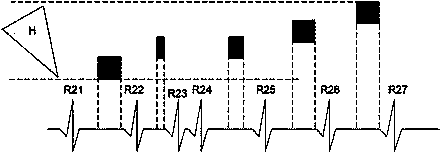
[0085] Embodiment 3: Helical scanning

[0086] Figure 8 It is a schematic flow chart of the control method of cardiac CT helical scanning in the third embodiment of the present invention. Such as Figure 8 As shown, the process mainly includes the following steps:

[0087] Step 801, determine the image scanning range of the heart.

[0088] Step 802: Determine the initial scanning position of the helical scanning according to the image scanning range.

[0089] Step 803, moving the patient examination table at a set speed.

[0090] Step 804, when the initial scanning position enters the scanning area, start scanning with low X-ray dose.

[0091] Step 805, detecting a first cardiac rhythm signal of the heart. After the first cardiac rhythm signal is detected, step 806 is performed.

[0092] In this embodiment, the first heart rhythm signal is a heartbeat signal of the heart. For example, the R wave signal on an electrocardiogram.

[0093] Step 806, judging whether the s...


PUM


Abstract

The invention discloses a control method and a control system for heart CT (computed tomography) and a CT machine. The method comprises the steps of determining the image scanning range of the heart; performing image data acquisition on each scanning segment in the image scanning range in a preset scanning viewing angle range in at least one heart quiescent period, wherein scanning viewing angles of image data in different heart quiescent periods corresponding to single scanning segment are not coincided and are equal to the preset scanning viewing angle range after being accumulated. By adopting the technical scheme disclosed by the invention, the image quality can be improved, and unnecessary X-ray radiation is reduced.

Description

technical field [0001] The invention relates to computer X-ray tomography (CT) imaging, in particular to a control method, system and CT machine for cardiac CT scanning. Background technique [0002] As a kind of medical equipment, CT machine is widely used in the medical and health field to assist doctors in imaging patients. figure 1 A structural schematic diagram of a current CT machine is shown in . Such as figure 1 As shown, the CT machine includes: a bottom supporting part 1, a CT gantry (gantry) 2, an X-ray tube 3, an X-ray detector 4, and a quasi-parameter arranged between the X-ray tube 3 and the X-ray detector 4. Straightener 5, control device 6 and image reconstruction device 7. [0003] Wherein, the CT gantry 2 is usually in a ring structure, and is installed on the bottom support member 1, and can rotate around its own axis. Normally, the direction parallel to the axis of the CT gantry 2 is called the Z direction, the horizontal direction perpendicular to th...

Claims


Application Information

Patent Timeline
IPC IPC(8): A61B6/03
Inventor 董建威
Owner SIEMENS SHANGHAI MEDICAL EQUIP LTD
Why Eureka
Try Eureka