Mopping vehicle

A technology of mopping vehicles and mopping tools, which is applied in the directions of road cleaning, construction, and cleaning methods, etc. It can solve the problems of difficult collection of waste, limited adsorption of dust on the ground, and difficulty in widespread popularization, etc., and achieves convenient operation and use. Embodiments Many, easy to promote the effect of implementation

Active Publication Date: 2014-05-21
ZHENGZHOU ZHONGYUE ELECTRICAL EQUIP CO LTD
View PDF7 Cites 11 Cited by
  • Summary
  • Abstract
  • Description
  • Claims
  • Application Information

AI Technical Summary

Problems solved by technology

However, this mopping vehicle uses a mopping roller and a mopping belt surrounding its outer surface to clean the ground, which has limited adsorption of dust on

Method used


Image

  • Mopping vehicle
  • Mopping vehicle
  • Mopping vehicle

Examples


Embodiment 1

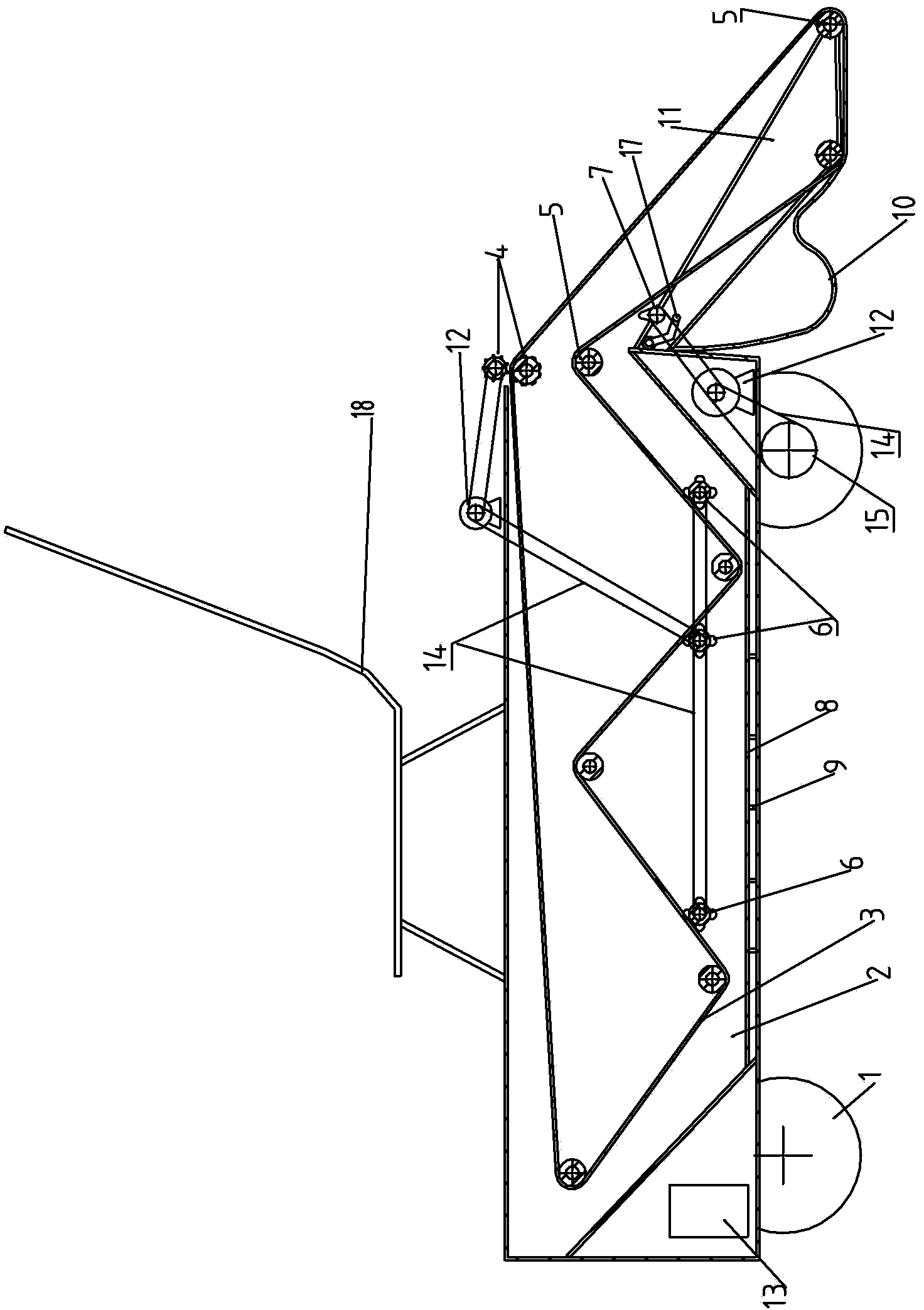
[0046] see figure 1 , Figure 6-11 , Figure 14 , 15 , in the figure, the mopping vehicle of the present invention includes a car body, wheels, a water tank, a ring drag tool, a transmission mechanism and a power mechanism, a water tank is provided in the vehicle body, and a group of washing shafts and a pair of drag shafts are arranged in the water tank. A set of guide shafts are respectively arranged inside and outside the water tank, wherein the guide shafts set outside the water tank are a row of guide shafts distributed horizontally, and one of the drag shafts is connected with the transmission mechanism, so that the ring-shaped puller passes through the dragging shaft in turn. Driven by the shaft and the guide shaft, they circulate in the water tank and on the ground respectively; the washing shaft is in contact with the lower surface of the ring mop, and one of the washing shafts is connected to the transmission mechanism; between the car body, the outside of the wate...

Embodiment 2

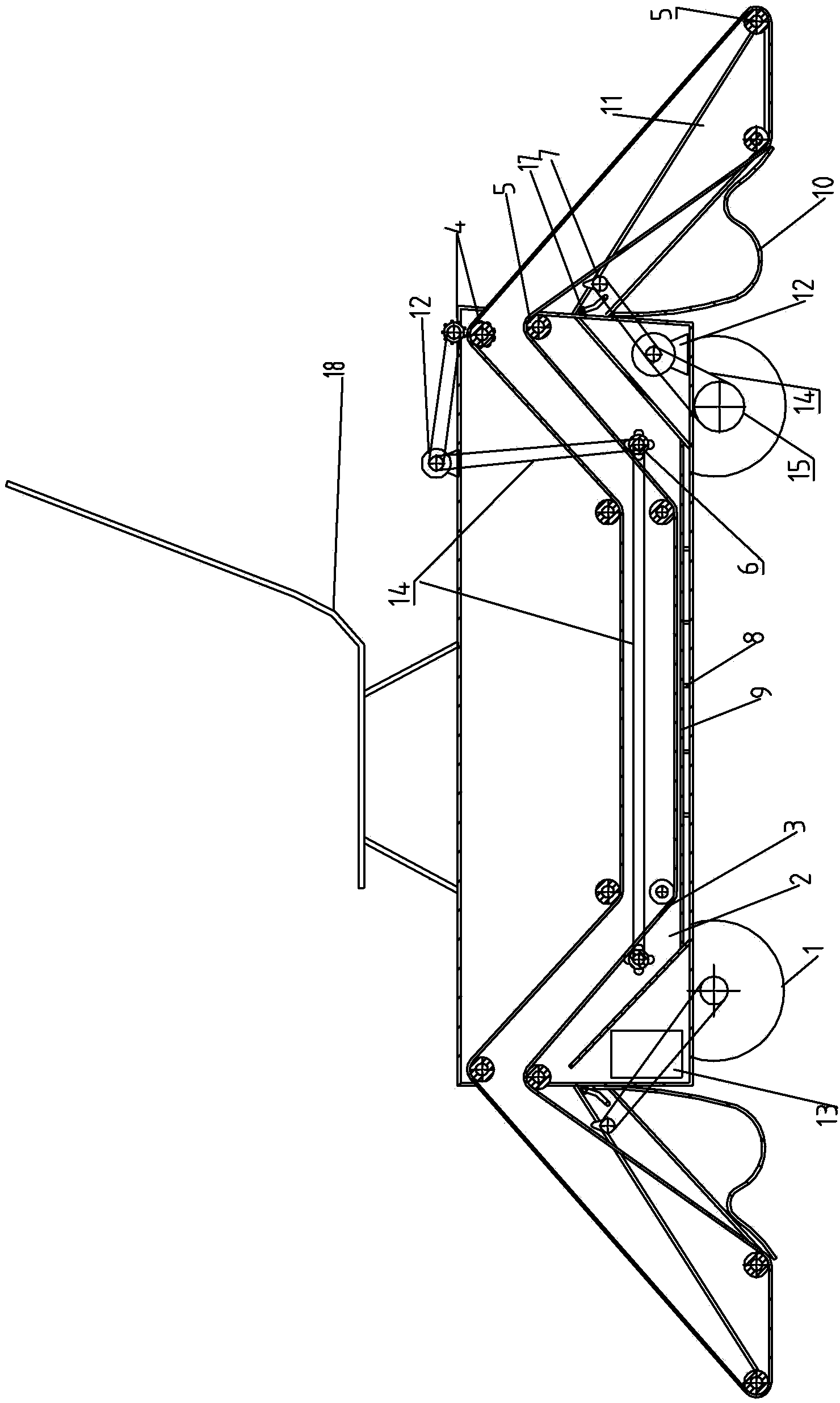
[0056] see figure 2 , the structure of this embodiment is similar to that of Embodiment 1. The same numbered parts in the figure represent the same meaning and will not be repeated here. The difference is that the guide shafts arranged outside the water tank in this embodiment are distributed on the front and rear sides of the car body , and the guide shaft brackets are respectively installed on the front and rear sides of the car body. A spring or rubber strip is provided between the lower part of the guide shaft bracket and the water tank to connect the guide shaft. It is in contact with the ground on both sides of the car body; at the same time, a handle is provided on one side of the guide shaft bracket, and the guide shaft bracket can be lifted up and down through the handle.

Embodiment 3

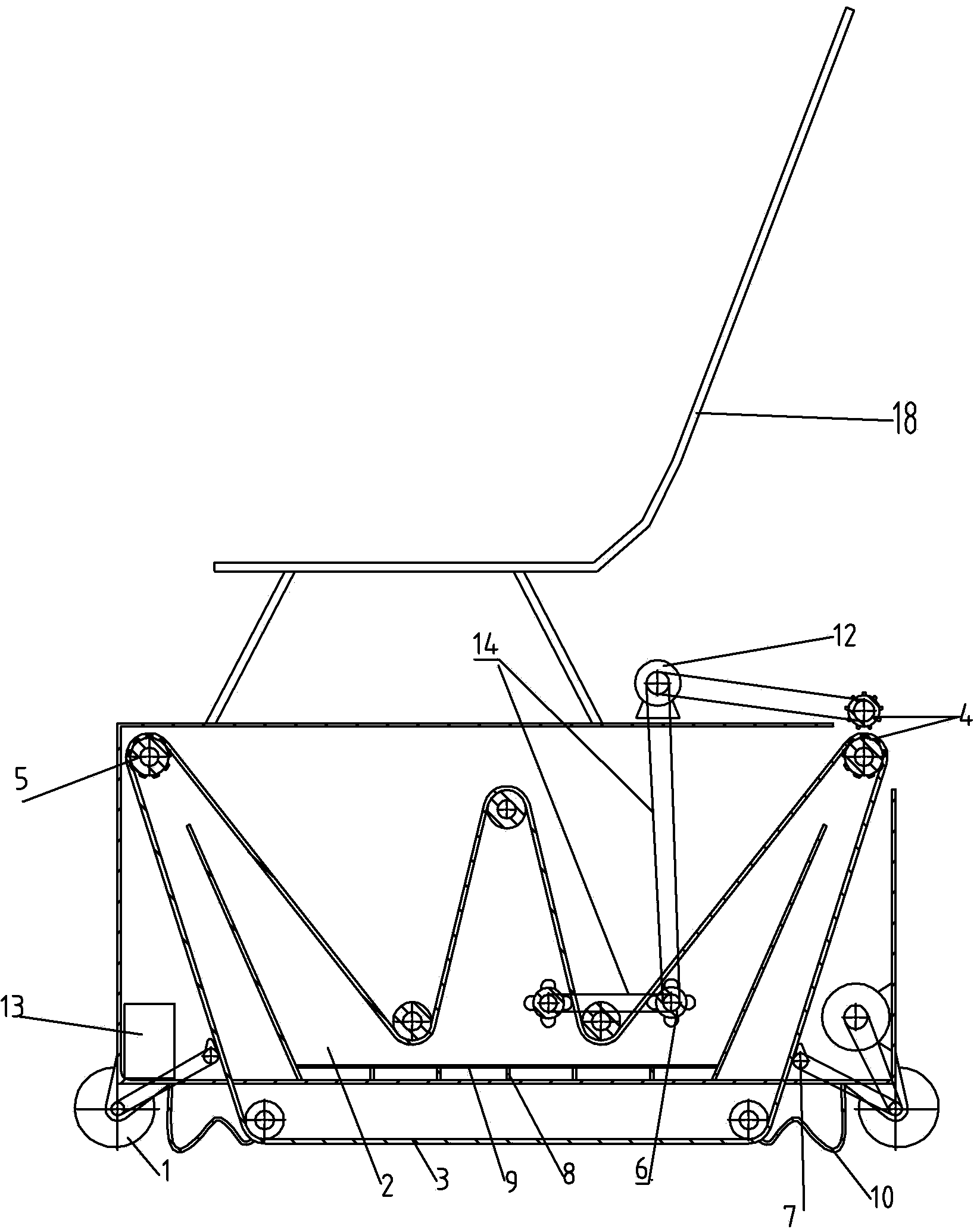
[0058] see image 3 , the structure of this embodiment is similar to that of Embodiment 1, and the same numbered parts in the figure represent the same meaning, which will not be repeated here. The ring-shaped drag tool bypasses the guide shaft and contacts with the ground below the car body.


PUM


Abstract

The invention belongs to the technical field of environment cleaning equipment, and particularly relates to a mopping vehicle. The mopping vehicle comprises a vehicle body, a water trough, an annular mopping tool, a power mechanism and a transmission mechanism, wherein the water trough is provided with at least one pair of dragging shafts, the power mechanism drives a dragging wheel to operate through the transmission mechanism, the annular mopping tool is driven to conduct circulation movement in the water trough and on the ground, and guide shafts used for regulating the moving direction of the annular mopping tool are arranged inside and outside the water trough. At least one set of cleaning shafts are arranged in the water trough, an object collecting device is arranged between the outer side of the water trough and the annular mopping tool, a beating shaft is arranged above the object collecting device, and the cleaning shafts and the beating shaft are all connected with the transmission mechanism and make contact with the outer surface of the annular mopping tool. The mopping vehicle can have multiple different specifications, can be widely used for cleaning the ground of various occasions, is simple in structure, easy to operate and convenient to maintain, has high social benefits and enterprise benefits, and has high popularizing value.

Description

technical field [0001] The invention belongs to the technical field of environmental cleaning equipment, in particular to a mopping vehicle. Background technique [0002] At present, the mopping vehicles that can be seen and purchased in China use rotating brushes to clean and collect dust and garbage into the memory while sprinkling water. Due to the function of sweeping, it can remove solid waste and some dust, but due to the adsorption effect of the ground and water, most of the fine dust, especially the 2.5ppm level, is difficult to remove. [0003] Chinese utility model patent CN02222825.X discloses a fully automatic floor mopping vehicle, including a floor mopping roller, a mopping belt, a driving roller wheel, a passive roller wheel, a car body, a steering wheel and a driving wheel, and the mopping roller is placed on the car body In the front, the car body is equipped with a remote control circuit board, battery and motor, the gears are fixed on the side of the driv...

Claims


Application Information

Patent Timeline
IPC IPC(8): E01H1/05
Inventor 赵松奇
Owner ZHENGZHOU ZHONGYUE ELECTRICAL EQUIP CO LTD
Why Eureka
Try Eureka