A special-shaped cantilevered steel structure and its construction method

A construction method and technology for steel structures, applied in special structures, building components, building structures, etc., can solve the problems of failure to meet the installation requirements of connection nodes, failure to meet load-bearing requirements, dangerous and complicated welding work, etc. Change, meet the load-bearing requirements of steel structures, and reduce the effect of self-weight

Active Publication Date: 2015-11-18
CHINA CONSTR SECOND ENG BUREAU LTD +1
View PDF9 Cites 1 Cited by
  • Summary
  • Abstract
  • Description
  • Claims
  • Application Information

AI Technical Summary

Problems solved by technology

[0004] The purpose of the present invention is to provide a special-shaped cantilevered steel structure and its construction method. To solve the shape of the curling cantilevered steel structure, due to the long cantilever distance, large handle size and heavy weight, ordinary cantilevered structures are used. and the connection form cannot meet the installation requirements of the connection nodes of the two, and the technical problems that cannot meet the load-bearing requirements
In addition, it is necessary to solve the technical problems that the pot handle is far away from the crane, and there are great difficulties in the installation process. The amount of welding at the pot handle is relatively large, the space is quite narrow, and the welding work is dangerous and complicated.

Method used


Image

  • A special-shaped cantilevered steel structure and its construction method
  • A special-shaped cantilevered steel structure and its construction method
  • A special-shaped cantilevered steel structure and its construction method

Examples


Embodiment Construction

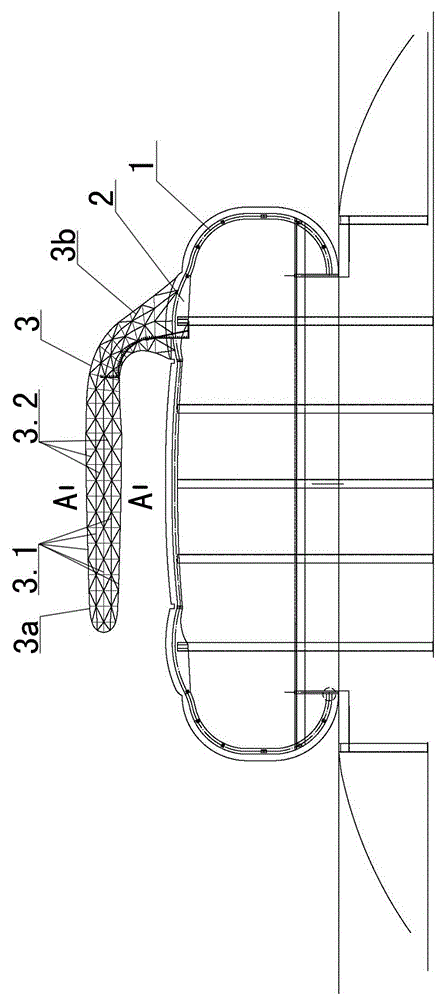
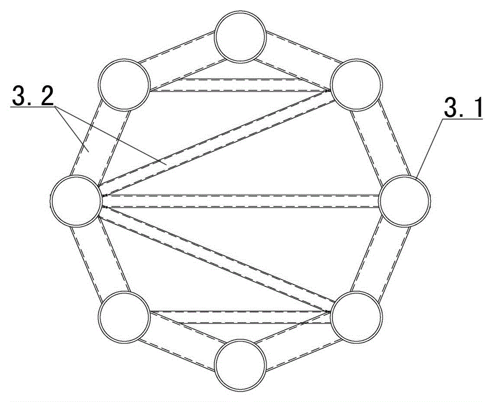
[0045] Examples see figure 1 As shown, a special-shaped overhanging steel structure, including a pot-shaped steel structure, is composed of a pot cup 1, a pot bolt connected to the top of the pot cup, and a pot handle 3 connected to the pot bolt; see figure 2As shown, the handle is a tubular truss composed of at least eight symmetrically distributed main rods 3.1 and webs 3.2 connecting the main rods. section and the other open end of the cantilever section 3a extends downwards into a funnel shape with a narrow top and a wide bottom, and is used for a support section 3b that is fixedly connected to the top side of the kettle bolt.

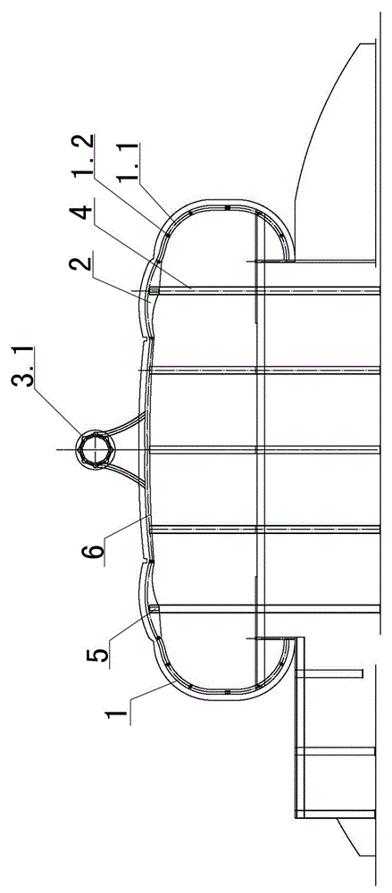
[0046] see image 3 and Figure 4 As shown, the pot cup 1 includes a vertical frame column 4 that is arranged at intervals inside the cup and surrounds a circle, a horizontal frame beam 5 connected between the tops of the frame column 4, and the outside of the frame beam 5 forms a cup body. The meridional curved columns 1.1, the weft curved bea...


PUM


Abstract

The invention discloses a special-shaped cantilevered steel structure. The special-shaped cantilevered steel structure comprises a pot-shaped body in a steel structure, wherein the pot-shaped body consists of a pot cup, a pot bolt connected with the top part of the pot cup, and a pot handle connected with the pot handle, wherein the pot handle comprises at least eight main rods which are distributed symmetrically and a tubular truss consisting of web rods connected among the main rods; the tubular truss comprises a cantilevered section and a support section, wherein the cantilevered section is cantilevered above the pot handle and has a closed end; the support section is in a hopper shape with narrow upper part and wide lower part which is formed by extending the other opening end of the cantilevered section downward and is used for fixedly connecting one side of the pot bolt. The construction method comprises the following steps: mounting the pot bolt and splicing the pot handle; determining the position of a main pipe; mounting wed rods; hanging the support section; mounting the cantilevered section; splicing the support section and the cantilevered section. By the special-shaped cantilevered steel structure and the construction method thereof, the technical problems that the mounting requirement of a connecting node cannot be met by using an ordinary cantilevered structure and an ordinary connecting form because the cantilevering distance is long, the pot handle is large in size and heavy in weight, and the weight bearing requirement cannot be met are solved.

Description

technical field [0001] The invention belongs to steel structure engineering, in particular to a special-shaped cantilevered steel structure and a construction method thereof. Background technique [0002] With the rapid development of modern architectural design, architectural appearance is becoming more and more diversified. The special-shaped steel structure in the shape of a curling pot includes a cup at the bottom, a bolt on the top, and a handle connected to the bolt. Compared with the shape of a regular round pot, the cross-section of the steel structure in the shape of a curling pot is larger. [0003] The pot handle is a large-span cantilever structure connected to the pot bolt. The cantilever distance is relatively long. The pot handle is large in size and heavy in weight. There are few connection points with the pot bolt (base steel structure), and there are no other support points except the pot bolt. , the ordinary cantilever structure and the connection form of...

Claims


Application Information

Patent Timeline
Patent Type & Authority Patents(China)
IPC IPC(8): E04B1/34E04G21/14
Inventor 张开武彭石磊张洪涛刘达琦郑晨曹金桥邹聪
Owner CHINA CONSTR SECOND ENG BUREAU LTD
Why Eureka
Try Eureka