Efficient heat exchange tube and evaporative condenser

A technology for evaporative condensers and heat exchange tubes, applied in evaporators/condensers, refrigerators, refrigeration components, etc., can solve the problems of low heat transfer coefficient and large wind resistance outside the tube, and achieve high heat transfer coefficient, Enhanced heat transfer performance and excellent heat resistance and thermal conductivity

Active Publication Date: 2014-05-21
HANGZHOU SHENSHI ENERGY CONSERVATION TECH
View PDF8 Cites 23 Cited by
  • Summary
  • Abstract
  • Description
  • Claims
  • Application Information

AI Technical Summary

Problems solved by technology

[0004] Therefore, the technical problem to be solved by the present invention is that the evaporative condensers in the prior art mostly use stainless steel straight tubes with relatively thick tube diameters, the heat transfer coefficient inside the tubes is not high, and the wind resistance outside the tubes is too large, providing a thermal conductivity Good, high-efficiency heat exchange tubes with small diameters

Method used


Image

  • Efficient heat exchange tube and evaporative condenser
  • Efficient heat exchange tube and evaporative condenser
  • Efficient heat exchange tube and evaporative condenser

Examples


Embodiment 1

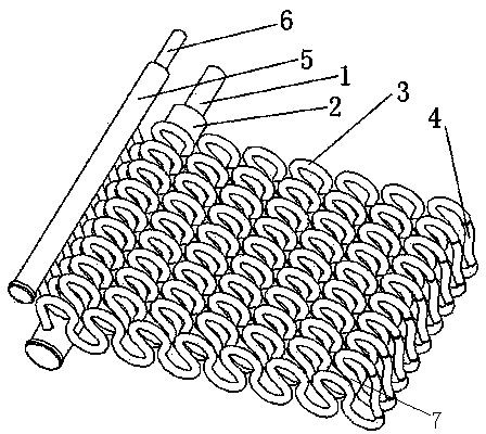
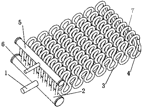
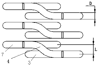
[0035] Such as figure 1 As shown, a high-efficiency heat exchange tube includes a gas collection pipe 2 and a liquid collection pipe 5, and several heat exchange tube units are communicated between the gas collection pipe 2 and the liquid collection pipe 5, and the heat exchange tube unit includes the first A heat exchange tube 3, a second heat exchange tube 7 and a corner elbow 4, the inlet of the first heat exchange tube 3 communicates with the collector 2, the outlet of the second heat exchange tube 7 communicates with the collector The liquid pipes 5 are connected, and the second heat exchange pipes 7 are arranged in layers and staggered up and down relative to the first heat exchange pipes 3, and the corner elbow 4 is arranged between the first heat exchange pipes 3 and the first heat exchange pipes 3. Between the second heat exchange tubes 7 , the outlet of the first heat exchange tube 3 is communicated with the inlet of the second heat exchange tube 7 . The setting of ...

Embodiment 2

[0040] An evaporative condenser includes a box body, a heat exchange coil, a fan, a water collecting pan, a circulating water pump and a spraying device, and the evaporative condenser includes the high-efficiency heat exchange tubes described above. The evaporative condenser involved in the present invention mainly adopts the above-mentioned high-efficiency heat exchange tubes with better thermal conductivity and smaller tube diameters.

[0041] In the evaporative condenser of the present invention, the refrigerant enters the gas collecting pipe 2 from the inlet connecting pipe 1, and flows through the "Ω" twisted heat exchange tube, and the diameter of the heat exchange tube is φ≤15mm. In this embodiment, , the heat exchange tubes include the first heat exchange tube 3 of upper and lower layers, the second heat exchange tube 7 and the corner elbow 4, the first heat exchange tube 3 and the second heat exchange tube The shape, size and arrangement of the heat pipes 7 are consis...


PUM


Abstract

The invention discloses an efficient heat exchange tube. The efficient heat exchange tube comprises a gas collecting tube and a liquid collecting tube. A plurality of heat exchange tube units are communicated between the gas collecting tube and the liquid collecting tube. Each heat exchange tube unit comprises a first heat exchange tube, a second heat exchange tube and a corner elbow. The inlets of the first heat exchange tubes are communicated with the gas collecting tube. The outlets of the second heat exchange tubes are communicated with the liquid collecting tube. The second heat exchange tubes are vertically layered and arranged in a staggered mode relative to the first heat exchange tubes. The corner elbows are arranged between the first heat exchange tubes and the second heat exchange tubes. The outlets of the first heat exchange tubes are communicated with the inlets of the second heat exchange tubes. The efficient heat exchange tube solves the problems that in the prior art, the heat exchange tubes of an evaporative condenser are low in inner side heat exchange coefficient and large in outer side wind resistance, and is good in heat conduction performance and small in tube diameter; the evaporative condenser is good in heat transfer performance, high in pressure resistance, compact in structure and small in occupied space.

Description

technical field [0001] The invention relates to a high-efficiency heat exchanger, in particular to an evaporative condenser. Background technique [0002] The evaporative condenser is the main heat exchange equipment in the refrigeration system. Its working principle is: the superheated high-pressure refrigerant gas discharged from the compressor in the refrigeration system passes through the condensing exhaust pipe in the evaporative condenser, and the high-temperature gaseous refrigerant and The spray water and air outside the exhaust pipe perform heat exchange. When the evaporative condenser is working, the spray water is transported by the pump to the water in the sump to the spray pipe at the top of the evaporative condenser, and sprayed to the outer surface of the condensing pipe through the nozzle to form a thin water film. The middle part of the water evaporates into water vapor after absorbing heat, and the rest falls into the sump for circulation by the water pump...

Claims


Application Information

Patent Timeline
Patent Type & Authority Applications(China)
IPC IPC(8): F28F1/00F25B39/04
Inventor 吴小辉沈卫立石景祯
Owner HANGZHOU SHENSHI ENERGY CONSERVATION TECH
Why Eureka
Try Eureka