Tubular heat exchanger and turbulence device thereof

A technology of tube heat exchanger and turbulence device, which is applied in the field of tube heat exchanger and turbulence device, and can solve the problems of fast attenuation, spring fatigue damage, and lack of reinforcement.

Active Publication Date: 2014-05-21
WEICHAI POWER CO LTD
View PDF5 Cites 6 Cited by
  • Summary
  • Abstract
  • Description
  • Claims
  • Application Information

AI Technical Summary

Problems solved by technology

[0005] However, in the above-mentioned turbulence device, the rotating vibration springs with different diameters are fixedly connected with the propeller, and when the propeller rotates, the rotating vibration springs with different diameters are driven to rotate synchronously, which is easy to cause fatigue damage to the springs; The distance is fixed, and the position of the propellers can be properly arranged according to the degree of attenuation of the eddy current in order to achieve the most

Method used


Image

  • Tubular heat exchanger and turbulence device thereof
  • Tubular heat exchanger and turbulence device thereof
  • Tubular heat exchanger and turbulence device thereof

Examples


Embodiment Construction

[0025] The core of the present invention is to provide a flow turbulence device for a tubular heat exchanger, which can have better flow turbulence effects under different medium flow rates, thereby having better flow turbulence performance. Another core of the present invention is to provide a tubular heat exchanger including the above-mentioned flow turbulence device.

[0026] In order to enable those skilled in the art to better understand the solution of the present invention, the present invention will be further described in detail below in conjunction with the accompanying drawings and specific embodiments.

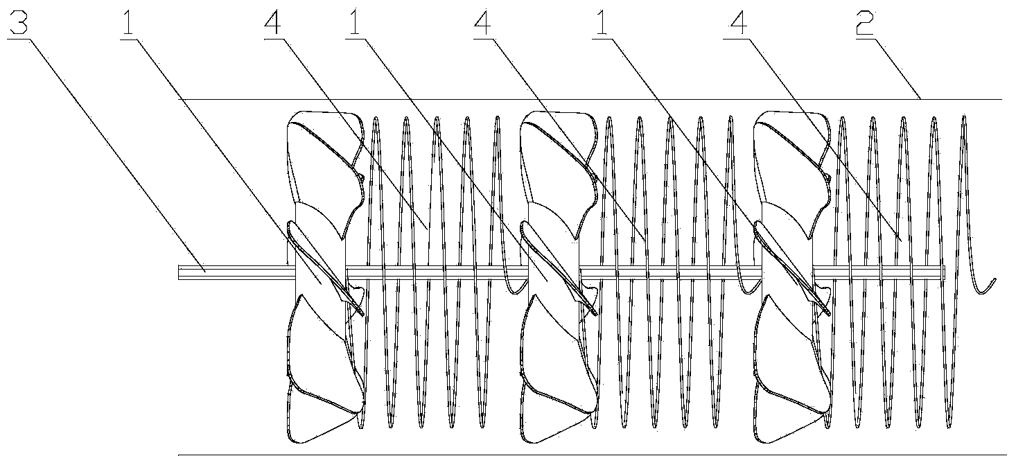
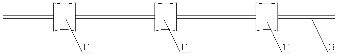
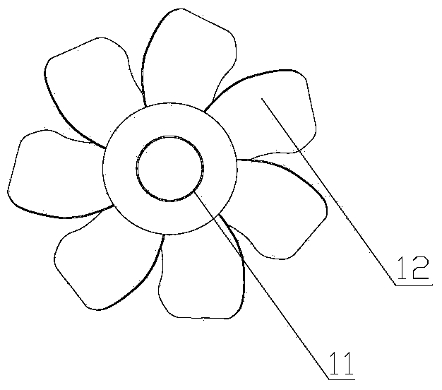
[0027] Please refer to figure 1 , figure 1 It is a structural schematic diagram of a specific embodiment of the flow turbulence device provided by the present invention.

[0028] In a specific embodiment, the flow turbulence device provided by the present invention is used in a tubular heat exchanger, and the flow turbulence device includes at least two vortex ge...


PUM


Abstract

The invention discloses a turbulence device used in a tubular heat exchanger. The turbulence device comprises at least two vertex generators and a fixed shaft which is arranged in a heat exchange tube of the tubular heat exchanger. The fixed shaft extends in the axial direction of the heat exchange tube. The fixed shaft is sleeved with each vertex generator in a clearance fit mode so that the vertex generators can move in the axial direction of the fixed shaft under the action of medium flow. An elastic component is installed between every two adjacent vertex generators. The deformation direction of each elastic component is the axial direction of the fixed shaft, so that axial locating of the vertex generators is realized through the elastic components. In this way, by means of selecting material parameters of the elastic components, namely when the flow velocity of the medium flow can be changed, the axial positions of every two adjacent vertex generators are adjusted in time, so that the turbulence device always has a good turbulence effect at different medium flow velocities, and therefore the turbulence performance of the turbulence device is improved. The invention further discloses the tubular heat exchanger comprising the turbulence device.

Description

technical field [0001] The invention relates to the technical field of heat exchange equipment, in particular to a flow turbulence device for a tube heat exchanger. The present invention also relates to a tubular heat exchanger comprising the above-mentioned flow turbulence device. Background technique [0002] As an important process equipment, tubular water heat exchangers are widely used in thermal power and diesel generator sets, petroleum smelting, metallurgy, papermaking and other industries. In order to improve the performance of the water heat exchanger, a turbulence device is often installed in the heat exchange tube to prevent the accumulation of scale on the tube wall, and to enhance the convective heat transfer efficiency of media of different temperatures in the tube side. [0003] Please refer to figure 1 , figure 1 It is a typical turbulence device used in tube heat exchangers. [0004] A typical turbulence device includes at least one section of different...

Claims


Application Information

Patent Timeline
IPC IPC(8): F28F13/12
Inventor 王云英乔海周赵晓嵩张有
Owner WEICHAI POWER CO LTD
Why Eureka
Try Eureka