Circulating cooling structure

A technology of circulating cooling and cooling structure, applied in the direction of cooling/ventilation devices, electrical components, electromechanical devices, etc., can solve the problems of motor performance degradation, sudden cooling and sudden heating of the shaft, damage to the motor shaft, etc., to reduce the damage Possibility, reducing the effect of damage factors, strengthening the filtering effect

Inactive Publication Date: 2014-05-21
CHENGDU DAMO PETROLEUM MACHINERY GRP
View PDF6 Cites 9 Cited by
  • Summary
  • Abstract
  • Description
  • Claims
  • Application Information

AI Technical Summary

Problems solved by technology

[0002] When oil is drilled, the motor of the drilling rig works continuously for a long time. Due to the high-speed friction between the motor shaft and the shaft sleeve, a large amount of heat energy will be generated. If the heat is not dissipated in time, the temperature will soon exceed the range and damage the shaft, which will eventually lead to a decline in the performance of the motor. or burned
At present, when cooling the motor shaft in China, cooling oil is only injected into the center hole of the motor shaft. Because this cooling method usually adopts an open cooling method, that is, the cooling medium added to the heat exchanger for heat exchange passes through the heat exchanger to transfer heat. After the exchange, it is directly discharged and cannot be recycled, thus causing great waste; and in the newly injected cooling oil, the temperature of the cooling oil cannot be stabilized, and the motor shaft itself maintains a certain temperature under long-term work. When the oil is injected into the motor shaft when the temperature is low, it is easy to cause the shaft to suddenly cool and heat, and eventually cause the motor shaft to be damaged

Method used


Image

  • Circulating cooling structure

Examples


Embodiment

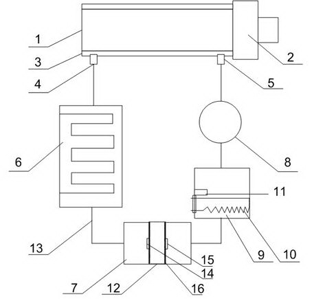
[0020] Such as figure 1 As shown, a circulating cooling structure of the present invention includes a motor main shaft 1, a shaft sleeve 2 is installed outside the motor shaft 1, a spiral groove 3 is arranged on the shaft sleeve 2, and an oil outlet 4 and an oil outlet 4 are opened at the bottom of the spiral groove 3 respectively. An oil inlet 5, a cooling structure and an oil temperature regulating mechanism connected to each other are installed between the oil outlet 4 and the oil inlet 5, and the cooling structure and the oil temperature regulating mechanism are connected to the oil inlet 5, The oil outlet 4 is connected; the cooling structure includes a heat exchanger 6, an oil collection chamber 7 and an oil pump 8, and the heat exchanger 6 is connected with the oil collection chamber 7 and the oil pump 8 through an oil guide pipe 13, and the A filter is also installed in the middle part of the oil chamber 7, and a drain valve can also be installed at the bottom of the o...


PUM


Abstract

The invention discloses a circulating cooling structure which comprises a motor spindle. A shaft sleeve is installed outside the motor spindle and provided with a spiral groove, the bottom of the spiral groove is respectively provided with an oil outlet and an oil inlet, and a cooling structure and an oil temperature adjusting mechanism which are connected with each other are installed between the oil outlet and the oil inlet and connected with the oil inlet and the oil outlet through oil conduits. Due to the oil temperature adjusting mechanism, under the treatment of the cooling structure, the temperature of cooling oil is controlled at the normally working temperature of the motor spindle before the cooling oil enters a spiral shaft, the influence factors causing the damage to the motor spindle are further reduced, and working stability of the motor spindle is guaranteed.

Description

technical field [0001] The invention relates to a motor, in particular to a circulating cooling structure. Background technique [0002] When oil is drilled, the motor of the drilling rig works continuously for a long time. Due to the high-speed friction between the motor shaft and the shaft sleeve, a large amount of heat energy will be generated. If the heat is not dissipated in time, the temperature will soon exceed the range and damage the shaft, which will eventually lead to a decline in the performance of the motor. or burnt. At present, when cooling the motor shaft in China, cooling oil is only injected into the center hole of the motor shaft. Because this cooling method usually adopts an open cooling method, that is, the cooling medium added to the heat exchanger for heat exchange passes through the heat exchanger to transfer heat. After the exchange, it is directly discharged and cannot be recycled, thus causing great waste; and in the newly injected cooling oil, th...

Claims


Application Information

Patent Timeline
IPC IPC(8): H02K9/19
Inventor 贺昶明
Owner CHENGDU DAMO PETROLEUM MACHINERY GRP
Why Eureka
Try Eureka