Hydraulic machine

A machine and hydraulic technology, applied in the direction of machines/engines, mechanical equipment, hydroelectric power generation, etc., can solve problems such as unsatisfactory results, and achieve the effect of improving service life, high efficiency, and low cost

Active Publication Date: 2014-05-21
VOITH PATENT GMBH
View PDF8 Cites 0 Cited by
  • Summary
  • Abstract
  • Description
  • Claims
  • Application Information

AI Technical Summary

Problems solved by technology

However, this solution also did not yield satisfactory results

Method used


Image

  • Hydraulic machine
  • Hydraulic machine
  • Hydraulic machine

Examples


Embodiment Construction

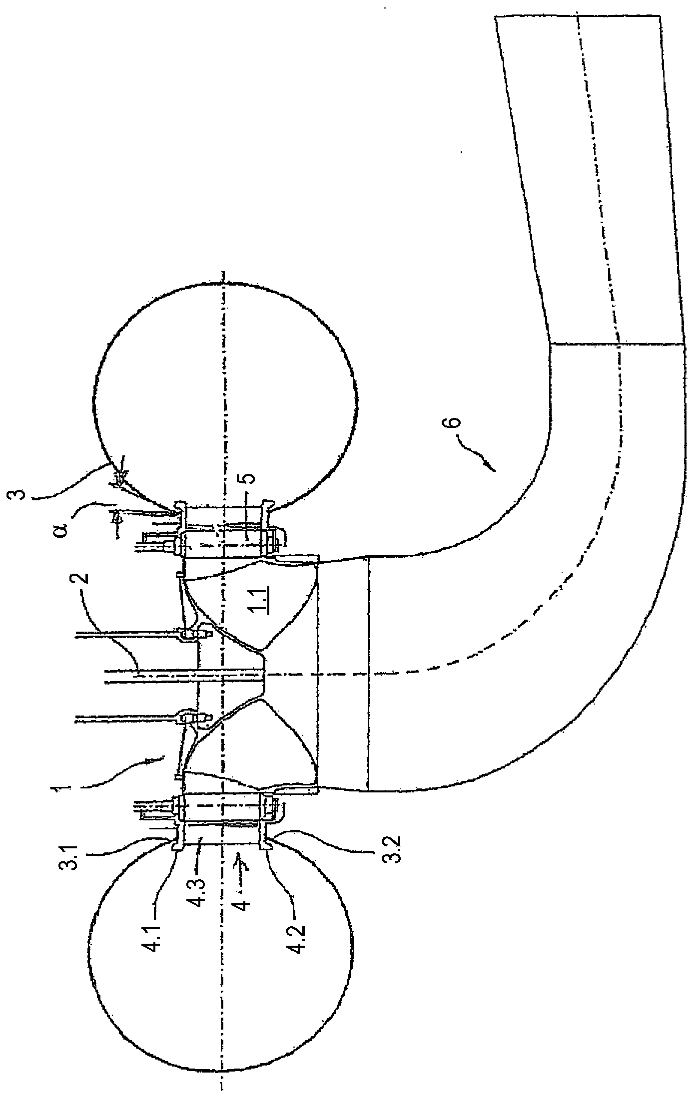
[0028] exist figure 1 The mixed flow turbine shown in has an impeller 1 . The impeller comprises a plurality of blades 1.1. The impeller 1 revolves around the axis of rotation 2 .

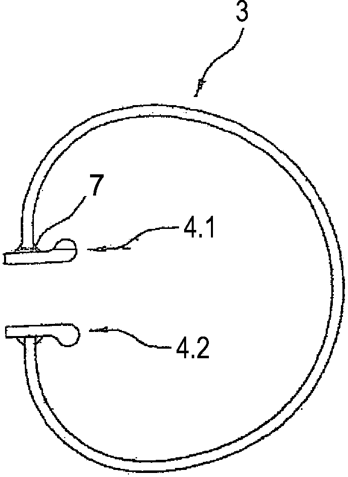
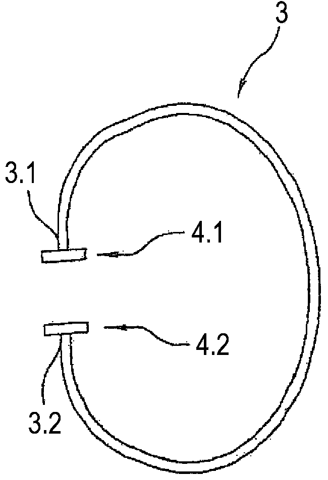
[0029] The impeller 1 is surrounded by a spiral housing 3 . The spiral housing 3 has, for example, a circular cross section. It has an annular groove-like opening towards the impeller 1 . The open groove is delimited by annular edges 3.1, 3.2.

[0030] The transverse ring 4 is connected to the annular groove formed by the edges 3.1, 3.2. The transverse ring has two transverse ring covers 4.1 and 4.2. The crossbeams 4.3 each serve as tie rods.

[0031] The region of the ring edges 3.1, 3.2 of the spiral housing is welded to the transverse ring cover 4.1, 4.2.

[0032] Between the transverse ring and the impeller, guides with guide vanes 5 are arranged.

[0033] Seen in the direction of flow, a suction pipe 6 is connected to the impeller 1 and has several sections.

[0034] As can be seen, ...


PUM


Abstract

The invention relates to a hydraulic machine having an impeller wheel (1) that comprises a plurality of impeller blades (1.1); having a spiral housing (3) that encloses the impeller wheel and that is open toward said impeller wheel by a circumferential slit formed by two circumferential edges (3.1, 3.2); having a traverse ring, comprising two traverse ring decks (4.1, 4.2) that are connected to one another by tension anchors (4.3); wherein the spiral housing is composed of segments that meet in the flow direction and that are welded to each other, the ends of which segments stand on the respective traverse ring deck (4.1, 4.2) and are welded to said deck; wherein at the meeting point (11) between two segments that are adjacent to one another and one traverse ring deck (4.1, 4.2) a stiffening element (10) is provided that protrudes into the inner space of the spiral housing (3); and wherein the extension of the stiffening element into the inner space of the spiral housing is so small that the flow is not affected in a significant manner.

Description

technical field [0001] The invention relates to a hydraulic machine, in particular a water turbine, a pump turbine or a pump, according to the preamble of claim 1 . This can be a Francis or Kaplan machine or other machines. Primarily it concerns machines with screw housings. Background technique [0002] As an example, reference may be made to US-A-4496282 or DE19950228A1. [0003] The helical casing of this machine surrounds the impeller. The spiral housing lies in a plane perpendicular to the axis of rotation of the impeller. Since the impeller shaft generally extends vertically, a horizontal plane is involved. The spiral shell is composed of segments. Seen in the direction of flow, the segments are connected and welded to each other. [0004] The spiral housing is open on its inner side towards the impeller. The spiral housing thus has a groove which surrounds the inner circumference of the spiral housing so that medium can flow from the spiral housing through the ...

Claims


Application Information

Patent Timeline
Patent Type & Authority Applications(China)
IPC IPC(8): F03B3/18F03B3/02F01D9/04F03B11/02F03B3/16
CPCF03B11/02F05B2230/232F03B3/02Y02E10/20Y02P70/50F03B3/186F03B11/04
Inventor 塞巴斯蒂安·希内克格哈德·温格特
Owner VOITH PATENT GMBH
Why Eureka
Try Eureka