Full-automatic feeder of punch press

A feeding machine and fully automatic technology, applied in the field of mechanical processing, can solve the problems of low efficiency, inaccurate product stamping, poor applicability, etc., and achieve the effect of high stamping efficiency and strong adaptability

Active Publication Date: 2014-05-28
DONGGUAN ZHUNRUI AUTOMATION EQUIP
View PDF8 Cites 15 Cited by
  • Summary
  • Abstract
  • Description
  • Claims
  • Application Information

AI Technical Summary

Problems solved by technology

[0002] At present, the flat sheet has two positioning holes to be stamped and formed. During the stamping and feeding process, the operator directly feeds the material to the positioning pin of the stamping die for processing. Practice has proved that this manual feeding method is not efficient. , strict requirements for operators, secondly, the safety factor of manual feeding is not high, and it is not uncommon for operators to be injured and disabled in the stamping feeding process, and thirdly, manual feeding requires heavy work intensity for operators
[0003] The existing punch feeder adopts the side-by-side positioning method when conveying the sheet-shaped products to be punched, and realizes it by fixing the corners. This side-side positioning method has the following disadvantages: 1. The cutting of the corners of the sheet-shaped semi-finished products is very strict, It needs to be cut quite neatly. If the cutting is not neat or the printed graphics are printed on the sheet material, the position will shift every time, and it cannot be accurately sent to the positioning pin of the punching die, resulting in the product not being punched properly during stamping. Accurate; 2. The existing punch feeder can only feed in one direction, which has poor applicability and low production capacity

Method used


Image

  • Full-automatic feeder of punch press

Examples


Embodiment Construction

[0014] The present invention will be further described below with reference to the accompanying drawings.

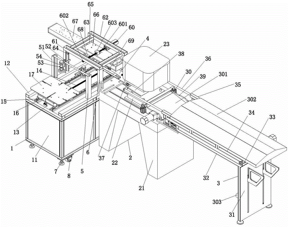
[0015] like figure 1 As shown, a fully automatic punch feeding machine includes a feeding device 1, a punching device 2 and a receiving device 3, one end of the punching device 2 is connected to the feeding device 1 through a punch connecting plate 4, and the other end of the punching device 2 is connected to the receiving device 3. The device 3 is connected, and the feeding device 1 includes a feeding machine platform 11, and the upper end of the feeding machine platform 11 is respectively provided with an installation base plate 12, and the installation base plate 12 is provided with an image positioning device 5 and a multi-directional feeding device 6, and the feeding machine platform 11 A screw positioning seat 13 is respectively provided at both ends of the middle part, and the two screw positioning seats 13 are connected by a first screw rod 14, and first guide ra...


PUM


Abstract

The invention discloses a full-automatic feeder of a punch press. The full-automatic feeder comprises a feeding device, a punching device and a collecting device. The feeding device comprises a feeding table, mounting base plates are respectively arranged on two sides of the upper end of the feeding table, an image positioning device and a multi-direction feeding unit are arranged on the mounting base plates, a screw positioning seat is arranged at each of two ends of the middle portion of the feeding table, the two screw positioning seats are connected via a first screw, two first guide rails are arranged on two sides of the first screw and connected via a positioning platform, and an initial positioning panel is arranged on the positioning platform. Poisoning marks on products are collected by a camera lens of the image positioning device, and after coordinate positions of the positioning marks are recorded by a computer and products to be punched is fed in, the coordinate positions of the positioning marks of the products to be punched are adjusted by the positioning platform to be identical with the coordinate positions of the positioning marks recorded by the computer, so that two positioning holes of each product to be punched can be ensured to be accurately suspended on two positioning pins of a punching die.

Description

technical field [0001] The invention relates to the field of mechanical processing, in particular to a fully automatic punch feeder. Background technique [0002] At present, the flat sheet has two positioning holes to be stamped and formed. During the stamping and feeding process, the operator directly feeds the material to the positioning pin of the stamping die for processing. Practice has proved that this manual feeding method is not efficient. , Strict requirements for operators, second, the safety factor of manual feeding is not high, and it is not uncommon for operators to be injured and disabled in the stamping feeding process, third, manual feeding, the operator's work intensity is high. [0003] The existing punch feeder adopts the side-by-side positioning method when conveying the sheet-shaped products to be punched, which is realized by fixing the corners. This side-side positioning method has the following disadvantages: 1. The cutting of the corners of the shee...

Claims


Application Information

Patent Timeline
Patent Type & Authority Applications(China)
IPC IPC(8): B21D22/00B21D43/00B21D43/18B21D43/20B21C51/00
Inventor 陈柏江
Owner DONGGUAN ZHUNRUI AUTOMATION EQUIP
Why Eureka
Try Eureka