
Pipe bar cutoff machine

A cutting machine and pipe rod technology, applied in the field of pipe rod processing, can solve the problems of low cutting precision, large force, large processing deformation, etc., and achieve the effect of small deformation, smooth cutting surface and not easy to deform.

Active Publication Date: 2014-05-28
宁国双宁机械有限公司
View PDF6 Cites 0 Cited by
  • Summary
  • Abstract
  • Description
  • Claims
  • Application Information

AI Technical Summary

Problems solved by technology

The core indicators in the cutting accuracy include the degree of deformation and the vertical angle of the end face. In the existing technology, when the cutting machine cuts the tube and bar, the large force often leads to large processing deformation and low cutting accuracy.

Method used


Image

  • Pipe bar cutoff machine

Examples


Embodiment Construction

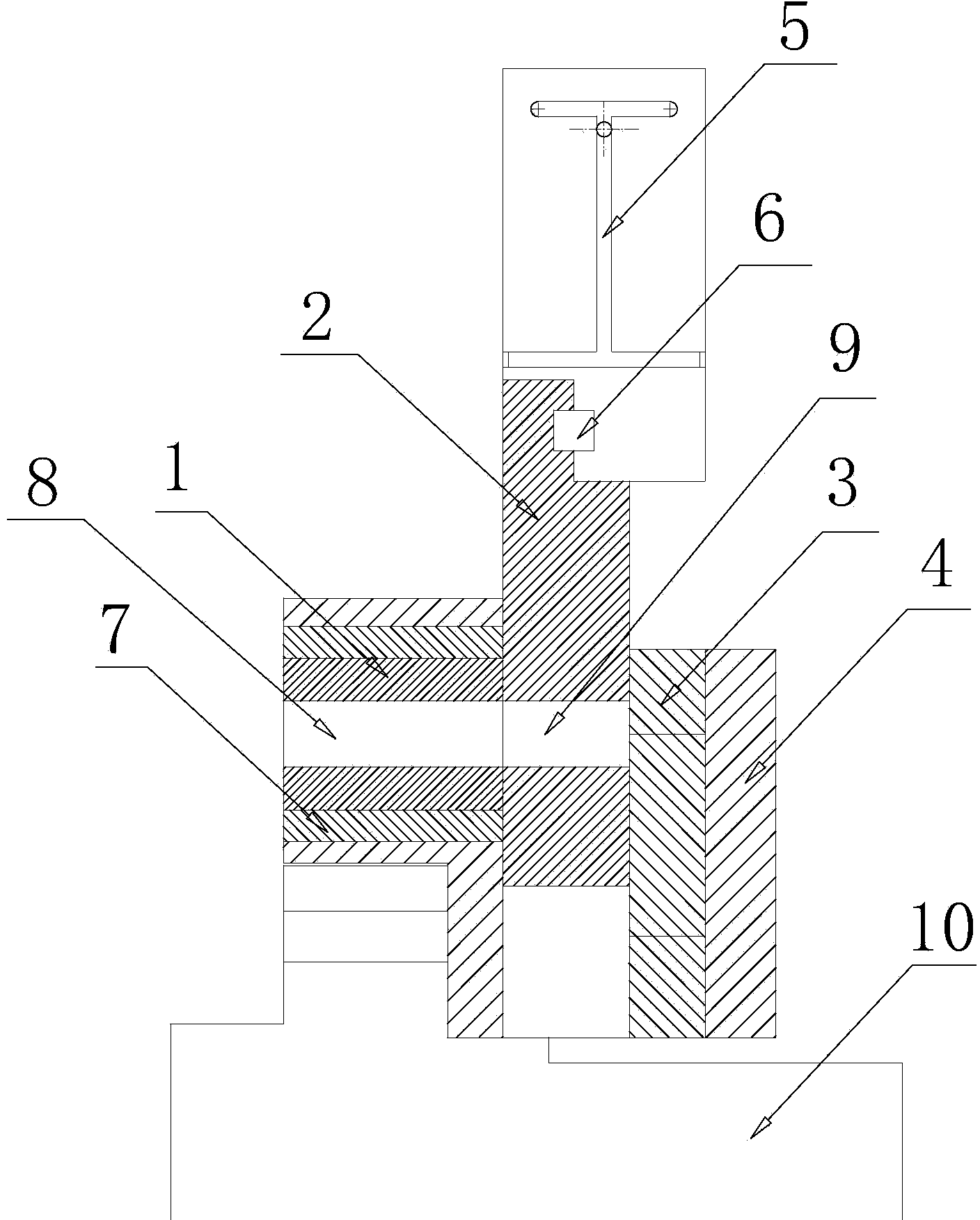
[0010] Such as figure 1 as shown, figure 1 It is a structural schematic diagram of a tube and rod cutting machine proposed by the present invention.

[0011] refer to figure 1 , a pipe and rod cutting machine proposed by the present invention is used to cut steel pipes or pipe rods, including a machine base 10, a mold core 1 fixed on the machine base 10, and a movable shearing seat is arranged on one side of the mold core 1 2. The side of the movable shear seat 2 away from the mold core 1 is provided with a cam 3, the side of the mold core 1 close to the movable shear seat 2, the two sides of the movable shear seat 2, and the side of the cam 3 close to the movable shear seat 2 The surface of the base is smooth, and the side of the master form 3 away from the movable shear seat 2 is provided with a formwork 4, the formwork 3 leans against the formwork 4, the formwork 4 is fixed on the machine base 10, and the mold core 1 is provided with a first cavity , the movable shear se...


PUM


Abstract

The invention discloses a pipe bar cutoff machine. The pipe bar cutoff machine comprises an engine base and a die core fixed on the engine base. A movable shearing seat is arranged at one side of the die core; one side, away from the die core, of the movable shearing seat is provided with a leaning die; the surface, close to one side of the movable shearing seat, of the die core, two sides of the movable shearing seat and one side, close to the movable shearing seat, of the leaning die are flat; one side, away from the movable shearing seat, of the leaning die is provided with a die set; the leaning die leans on the die set fixed on the engine base; a first cavity body is arranged in the die core; a second cavity body is arranged in the movable shearing seat; the inner diameters of the first and second cavity bodies are equal to the outer diameter of an object to be cut off; the positions, close to the second cavity body, at two sides of the movable shearing seat are provided with edges; a driving mechanism for driving the movable shearing seat to move up and down is arranged above the movable shearing seat; when the central axis of the first cavity body and the central axis of the second cavity body are positioned in the same position, the distance between the bottom of the movable shearing seat and the engine base is larger than the inner diameter of the second cavity body.

Description

technical field [0001] The invention relates to the technical field of pipe and rod processing, in particular to a pipe and rod cutting machine. Background technique [0002] In the production process, it is often necessary to cut long tubes and rods into specified sizes. Usually, a cutting machine or a shearing machine is used to process the long-sized pipe and bar into a specified size through the action of shearing force. Generally, the cutting accuracy is used as the standard to judge the processing quality. The core indicators of the cutting accuracy include the degree of deformation and the vertical angle of the end face. In the prior art, when the cutting machine cuts the tube and bar, the large force often leads to large processing deformation and low cutting accuracy. Contents of the invention [0003] In order to solve the technical problems existing in the background technology, the present invention proposes a pipe and rod cutting machine, which realizes high...

Claims


Application Information

Patent Timeline
IPC IPC(8): B21D28/02B21D28/14
Inventor 苏荣建
Owner 宁国双宁机械有限公司
Learn More