Method for judging ever-burning of torch ever-burning lamp

A technology of long-bright lights and torches, which is applied in the direction of using electric radiation detectors for photometry, etc., can solve problems such as effective use and unstable output signals, achieve good technical effects, improve reliability, and output signals are stable and reliable.

Active Publication Date: 2014-05-28
CHINA PETROLEUM & CHEM CORP +1
View PDF4 Cites 1 Cited by
  • Summary
  • Abstract
  • Description
  • Claims
  • Application Information

AI Technical Summary

Problems solved by technology

[0006] The technical problem to be solved by the present invention is that the thermocouple, ultraviolet and infrared detection technology in the prior art cannot be effectively used in harsh environments, and the output signal is unstable, and a new method for judging the long-burning of the torch lamp is provided

Method used


Image

  • Method for judging ever-burning of torch ever-burning lamp

Examples


Embodiment 1

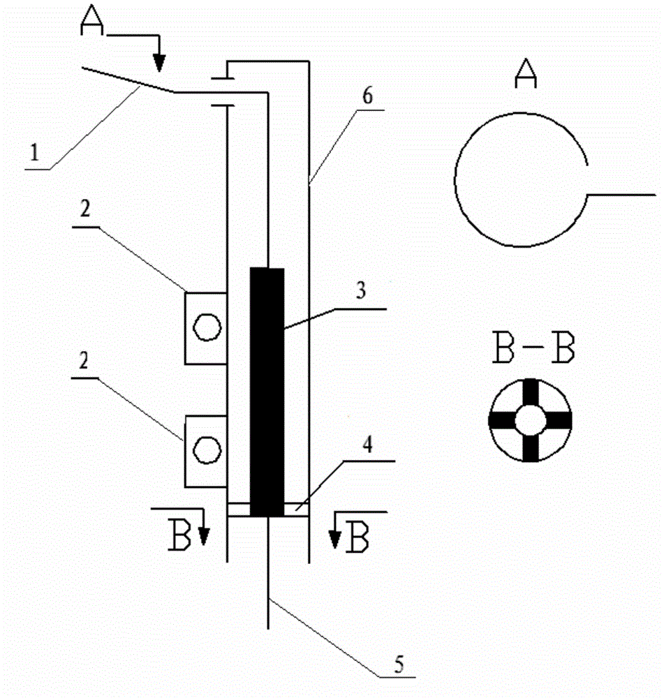
[0018] figure 1 It is a schematic diagram of the structure of the detector according to the present invention. The detector includes a probe 1, a high temperature-resistant insulating ceramic 3, a casing 6, a mounting rib 2, a connecting rib 4, and a high-temperature cable 5. The casing 6 is a cylinder. One end of the needle 1 is located outside the casing 6, and the other end is connected to the high temperature cable 5. The high temperature cable 5 is located outside the casing 6, and the part of the probe 1 inside the casing 6 is wrapped with a high temperature insulating ceramic 3, which is fixed by the connecting rib 4. Inside the casing 6, to ensure the insulation between the casing and the probe under harsh working conditions such as high temperature, the outer side of the casing 6 is provided with a mounting rib 2 to connect with the permanent light, and the part of the probe 1 located on the outer side of the casing 6 is provided with a certain upward angle, and the an...

Embodiment 2

[0023] figure 1 It is a schematic diagram of the structure of the detector according to the present invention. The detector includes a probe 1, a high temperature-resistant insulating ceramic 3, a casing 6, a mounting rib 2, a connecting rib 4, and a high-temperature cable 5. The casing 6 is a cylinder. One end of the needle 1 is located outside the casing 6, and the other end is connected to the high temperature cable 5. The high temperature cable 5 is located outside the casing 6, and the part of the probe 1 inside the casing 6 is wrapped with a high temperature insulating ceramic 3, which is fixed by the connecting rib 4. Inside the casing 6, to ensure the insulation between the casing and the probe under harsh working conditions such as high temperature, the outer side of the casing 6 is provided with a mounting rib 2 to connect with the permanent light, and the part of the probe 1 located on the outer side of the casing 6 is provided with a certain upward angle, and the an...

Embodiment 3

[0028] figure 1 It is a schematic diagram of the structure of the detector according to the present invention. The detector includes a probe 1, a high temperature-resistant insulating ceramic 3, a casing 6, a mounting rib 2, a connecting rib 4, and a high-temperature cable 5. The casing 6 is a cylinder. One end of the needle 1 is located outside the casing 6, and the other end is connected to the high temperature cable 5. The high temperature cable 5 is located outside the casing 6, and the part of the probe 1 inside the casing 6 is wrapped with a high temperature insulating ceramic 3, which is fixed by the connecting rib 4. Inside the casing 6, to ensure the insulation between the casing and the probe under harsh working conditions such as high temperature, the outer side of the casing 6 is provided with a mounting rib 2 to connect with the permanent light, and the part of the probe 1 located on the outer side of the casing 6 is provided with a certain upward angle, and the an...


PUM


Abstract

The invention relates to a method for judging ever-burning of a torch ever-burning lamp and mainly solves the problem that in the prior art, a flame ion detector cannot be effectively used in the severe environment. According to the method for judging ever-burning of the torch ever-burning lamp, the ever-burning lamp is internally provided with a flame ion detector, wherein the flame ion detector comprises a probe (1), a high-temperature-resistant insulation ceramic (3), a housing (6) and a high-temperature-resistant cable (5); one end of the probe (1) is arranged outside the housing (6), and the other end is connected with the high-temperature-resistant cable (5); the high-temperature-resistant cable (5) is arranged outside the housing (6); and the periphery of the probe (1) in the housing (6) is partially wrapped with the high-temperature-resistant insulation ceramic (3). The above technical scheme well solves the above problem, and the method can be used in flame detection of the torch ever-burning lamp.

Description

technical field [0001] The invention relates to a method for judging the long-burning of a torch long-burning lamp. technical background [0002] Flare system is an important facility for refining and chemical enterprises, and its main function is to burn off the gas discharged from the start-up and shutdown of the device and in emergency state. Under normal circumstances, in order to burn the gas discharged from the device as soon as possible, a long-burning light is installed on the top of the torch. [0003] At present, the flame detection technology of torch luminaire mainly includes thermocouple, ultraviolet, infrared, etc., which are not perfect. Flame ion detection technology is a relatively new flame detection technology, which is based on the principle of unidirectional conductivity of flame, and has certain applications in relatively stable combustion fields such as gas stoves and boilers. However, since the torch light is installed at an altitude of more than 10...

Claims


Application Information

Patent Timeline
IPC IPC(8): G01J1/42
Inventor 于安峰张杰东刘华炜韩中枢党文义王鹏
Owner CHINA PETROLEUM & CHEM CORP
Why Eureka
Try Eureka