A remote network unified phase color identification system

A remote network, unified technology, applied in the field of remote network unified phase-color identification system, can solve the problems of one-time reverse connection of transformer phase sequence, inability to complete grid-connected operation, loss of human and financial resources, etc., to achieve accurate power supply and reduce repeated purchases , the effect of avoiding property damage

Active Publication Date: 2017-03-15
STATE GRID CORP OF CHINA +2
View PDF5 Cites 0 Cited by
  • Summary
  • Abstract
  • Description
  • Claims
  • Application Information

AI Technical Summary

Problems solved by technology

[0004] The inconsistency of the line identification above 35kV leads to the reversal of the phase sequence of the transformer at the first stage, and causes a 60° angle difference between the two secondary power systems, resulting in the inability to complete the grid-connected operation of the secondary system. To solve this problem, the power supply line needs to be large Power outage in the area, and reconnecting the phase sequence of the transformer again will cause human and financial losses
[0007] The phasing work is carried out according to the order of the commander. The high-voltage operator fixes the high-voltage lead wire on the insulating rod, and the length is appropriate. When the high-voltage wire is used to touch the high-voltage power point with the insulating rod, the movements are coordinated, and the two take care of each other to avoid mistakes and cause danger. , the problem with this method is that for high-voltage lines, especially for phase detection of high-voltage overhead lines, two devices are required to be in contact with two wires at the same time, and it is inconvenient to use the wired method, and it has certain risks
However, wireless phasing has geographical limitations, and the phasing range is very small, and it is impossible to complete phasing for power line networks that are far away.

Method used


Image

  • A remote network unified phase color identification system
  • A remote network unified phase color identification system
  • A remote network unified phase color identification system

Examples


Embodiment Construction

[0022] The present invention will be further described below in conjunction with the accompanying drawings and embodiments. While the invention will be described in conjunction with the preferred embodiments, it will be understood that it is not intended to limit the invention to the described embodiments. On the contrary, the invention is to cover alternatives, modifications and equivalents, which may be included within the scope of the invention as defined by the appended claims.

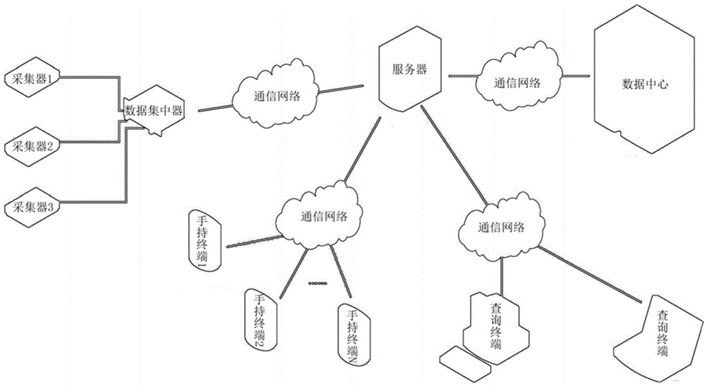
[0023] see figure 1 as shown,

[0024] 1. Acquisition base station: take power frequency three-phase power A, B, C as the reference source of phase color identification, and use system software to provide multi-directional services and functions. The remote network unified phase color identification system relies on the two major communication platforms of mobile communication network and the Internet, and the phase color marking handheld terminal has the network access function of TCP / IP, so as...


PUM


Abstract

The invention discloses a remote network unified phase color identification system which comprises an acquisition device, a data concentrator, a server, a data center, a handheld terminal which is used for a data acquisition test and a query terminal. The data concentrator is set in the range of a power grid or a sub power grid. The data concentrator is connected with the server. The server provides a network server and a database connection server. The system provided by the invention has the advantages that the remote network unified phase color identification system is based on two communication platforms of a mobile communication network and the Internet; automatic data transmission is realized through the networks; phase color identification unification of a power system is realized; closed loop power supply is accurate; the reliability and the economic benefit of power supply are improved; personnel input in a phase checking process and unnecessary economic loss in a construction process are reduced; and historical data query can be provided, which is convenient for an operator to timely and accurately carry out phase checking and construction result query.

Description

technical field [0001] The invention relates to a phase color identification system, more specifically, it relates to a remote network unified phase color identification system. Background technique [0002] Major cities in China, especially provincial capitals, special zone cities, central cities, etc., have gradually moved toward developed countries and regions (such as New York, Tokyo, and Hong Kong with a power supply reliability rate of over 99.99%, and an average annual power outage of more than ten minutes. In the face of strong demand, the safe and stable operation of the power grid must be guaranteed. The basic status of the power industry and the particularity of power production determine that the safe operation of the power grid must be ensured. [0003] There are many links involved in the safety of the power grid. In the power construction, a large number of switch stations, ring network cabinets, and power cables have been put into use. In addition, some old o...

Claims


Application Information

Patent Timeline
Patent Type & Authority Patents(China)
IPC IPC(8): G01R25/00G01R29/18
Inventor 汪志奕李振华卢海权王泽盼马龙君马志进贾海源张捷华卢斌
Owner STATE GRID CORP OF CHINA
Why Eureka
Try Eureka