
A Method for Sparse Estimation of Remote Sensing Image Based on Hybrid Transformation

A remote sensing image and hybrid transformation technology, which is applied in the field of remote sensing image processing, can solve the problems of loss of image detail information, difficulty in obtaining better sparse effect of remote sensing image, etc., and achieve good sparse effect

Active Publication Date: 2016-09-14
严格集团股份有限公司
View PDF0 Cites 0 Cited by
  • Summary
  • Abstract
  • Description
  • Claims
  • Application Information

AI Technical Summary

Problems solved by technology

[0004] In order to solve the problem that the existing sparse method can only retain most of the energy of the image, it is easy to cause the loss of image detail information, and it is difficult to obtain a better sparse effect for remote sensing images with rich details, a remote sensing based on hybrid transformation is provided. Image Sparse Estimation Methods

Method used


Image

  • A Method for Sparse Estimation of Remote Sensing Image Based on Hybrid Transformation
  • A Method for Sparse Estimation of Remote Sensing Image Based on Hybrid Transformation
  • A Method for Sparse Estimation of Remote Sensing Image Based on Hybrid Transformation

Examples


specific Embodiment approach 1

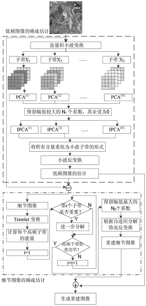
[0017] Specific Embodiment 1: A method for sparse estimation of remote sensing images based on hybrid transformation described in this embodiment, a method for sparse estimation of remote sensing images based on hybrid transformation, the method is implemented according to the following steps:

[0018] Step 1. Sparsely estimate the low frequency of the remote sensing image:

[0019] Step 1 (1), perform tensor product wavelet transform on the original image; Step 1 (2), use p-fold extraction filter to perform polyphase decomposition on each subband; Step 1 (3), perform decomposed component Principal component transformation; step 1 (4), retaining N for the transformed image 1 a larger transformation coefficient, and set the remaining coefficients to 0; get the result of sparse estimation, and inverse transform the above result;

[0020] Step 2. Sparsely estimate the high frequency of the remote sensing image:

[0021] Step 2 (1), subtract the original image from the low-frequ...

specific Embodiment approach 2

[0023] Embodiment 2: The difference between this embodiment and Embodiment 1 is that the sparse process of the low-frequency part of the remote sensing image is as follows: the original image is

[0024] The specific implementation process of step 1 (1) is as follows: Let A represent the two-dimensional tensor product wavelet transform, and the result of X after the tensor product wavelet transform represents XA T , the transformed image is expressed as:

[0025] XA T :=[(XA T ) (1) ,(XA T ) (2) ,…,(XA T ) (N) ]

[0026] In the formula, ":=" means "defined as", and N means the number of wavelet subbands;

[0027] The specific implementation process of step one (two) is: for each sub-band (XA T ) (i) The wavelet coefficients of the p-fold filter are used to generate transformation components, where i=1,...,N; the process is expressed as: symbol" "Indicates that after the variable before the sign is processed, it can be expressed as the variable after the sign; p...

specific Embodiment approach 3

[0035] Embodiment 3: The difference between this embodiment and Embodiment 1 or 2 is that after Step 1 (4) is completed, Step 1 (5) is performed: the estimation of the low-frequency part of the remote sensing image is carried out according to the following steps of:

[0036] Step 1. Apply principal component inverse transformation to each transformed component sequence Among them, i=1,2,...,N, the process is expressed as:

[0037] [ B ( 1 ) - 1 Y ~ ( 1 ) , B ( 2 ) - 1 Y ~ ( ...


PUM


Abstract

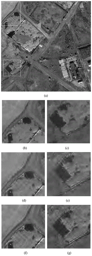
The invention discloses a remote sensing image sparseness estimation method based on mixing transformation, which belongs to the technical field of remote sensing image processing, and solves the problem that image detail information is lost and a good sparse effect of a remote sensing image with rich details is difficultly obtained as the majority of image energy is mainly retained in an existing sparseness estimation method. The method combines the advantages of smooth image presentation based on tensor product wavelet transform and the characteristic of effective expression of detail information such as texture and edge of Tetrolet transform, has no limitation on image characteristics, and has certain universality. An experimental result shows that in comparison with a simple remote sensing image sparseness estimation method, the method based on the mixing transformation can be used for effectively performing sparse representation on the remote sensing image. The method is specially suitable for sparseness treatment on remote sensing images.

Description

technical field [0001] The invention relates to a remote sensing image sparse estimation method, which belongs to the technical field of remote sensing image processing. Background technique [0002] Most of the existing image sparse estimation methods can achieve the best performance when the image has certain characteristics. For example, the tensor product wavelet transform can perform the best sparse representation for smooth images, but cannot describe the geometric features in the image well. Directional wavelet can better describe some detailed features of the image. For example, directionlet can better represent the intersecting lines in the image, and wedgelet can effectively detect the lines and surfaces in the image. But the ability of directional wavelet to represent smooth image is not as good as tensor product wavelet transform. Therefore, in order to effectively sparsely represent images, we need to judge the characteristics of the image first. However, it ...

Claims


Application Information

Patent Timeline
Patent Type & Authority Patents(China)
IPC IPC(8): G06T5/00
Inventor 石翠萍张钧萍张晔陈浩
Owner 严格集团股份有限公司
Learn More