
Cruise control method for tripod head video camera

A PTZ camera, cruise control technology, applied in image communication, TV, color TV components and other directions, can solve the problems of limited field of view, inability to track accurately, affecting monitoring effect, etc., to achieve good monitoring effect, convenient observation and The effect of judgment

Active Publication Date: 2014-05-28
ZHEJIANG UNIVIEW TECH CO LTD
View PDF4 Cites 48 Cited by
  • Summary
  • Abstract
  • Description
  • Claims
  • Application Information

AI Technical Summary

Problems solved by technology

[0006] The field of view is limited; the user cannot intuitively see all the areas that the PTZ camera can monitor, especially for the 360-degree rotating PTZ camera, when the user rotates the PTZ camera by moving the track point on the monitoring screen, it is difficult to rotate the PTZ camera from different angles. It is not conducive to the overall observation and judgment
[0007] The rotation of the pan / tilt is discontinuous; in the above scheme, the pan / tilt camera is turned from the static state to the designated position at the fastest speed each time, and then it is in a static state again. It is difficult to observe, so it will affect the actual monitoring effect
[0008] The response is not timely; when the moving target object moves very fast, the PTZ camera needs to turn from the static state to the designated position at the fastest speed, and the acceleration time is long, which may cause the PTZ camera to Has not rotated to the target position, resulting in inaccurate tracking

Method used


Image

  • Cruise control method for tripod head video camera
  • Cruise control method for tripod head video camera
  • Cruise control method for tripod head video camera

Examples


Embodiment Construction

[0020] In order to make the purpose, technical solutions and advantages of the embodiments of the present invention clearer, the technical solutions in the embodiments of the present invention will be clearly described below in conjunction with the accompanying drawings in the embodiments of the present invention. Obviously, the described embodiments are the Some, but not all, embodiments are invented. Based on the embodiments of the present invention, all other embodiments obtained by persons of ordinary skill in the art without making creative efforts belong to the protection scope of the present invention.

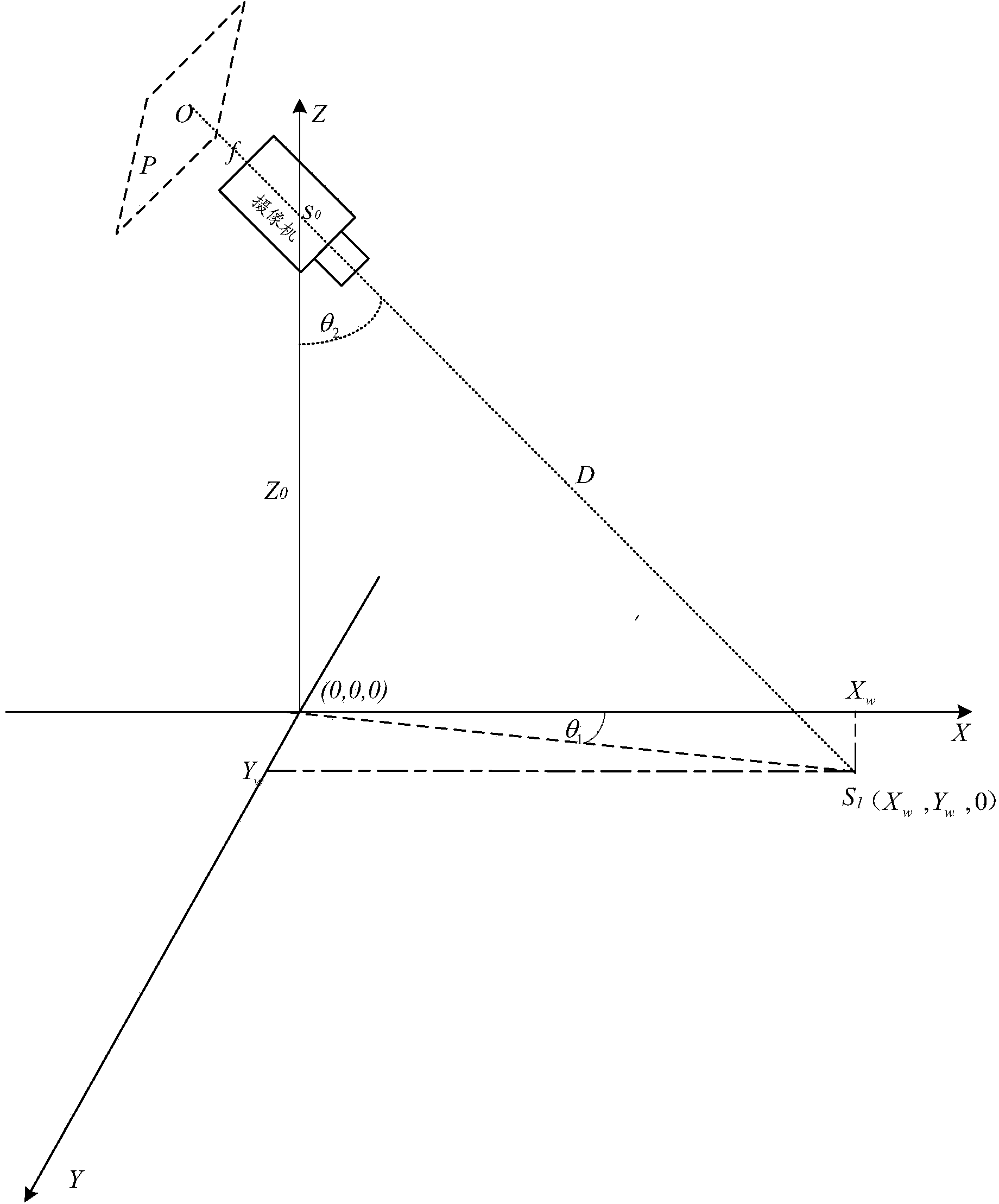
[0021] Before introducing the PTZ camera cruise control method provided in this embodiment, first refer to figure 1 Introduce relevant professional terms that may be involved:

[0022] Image coordinate system: digital images can be stored as an array in the computer, and the value of each element (ie pixel) in the array is the gray value of the image point; define a Ca...


PUM


Abstract

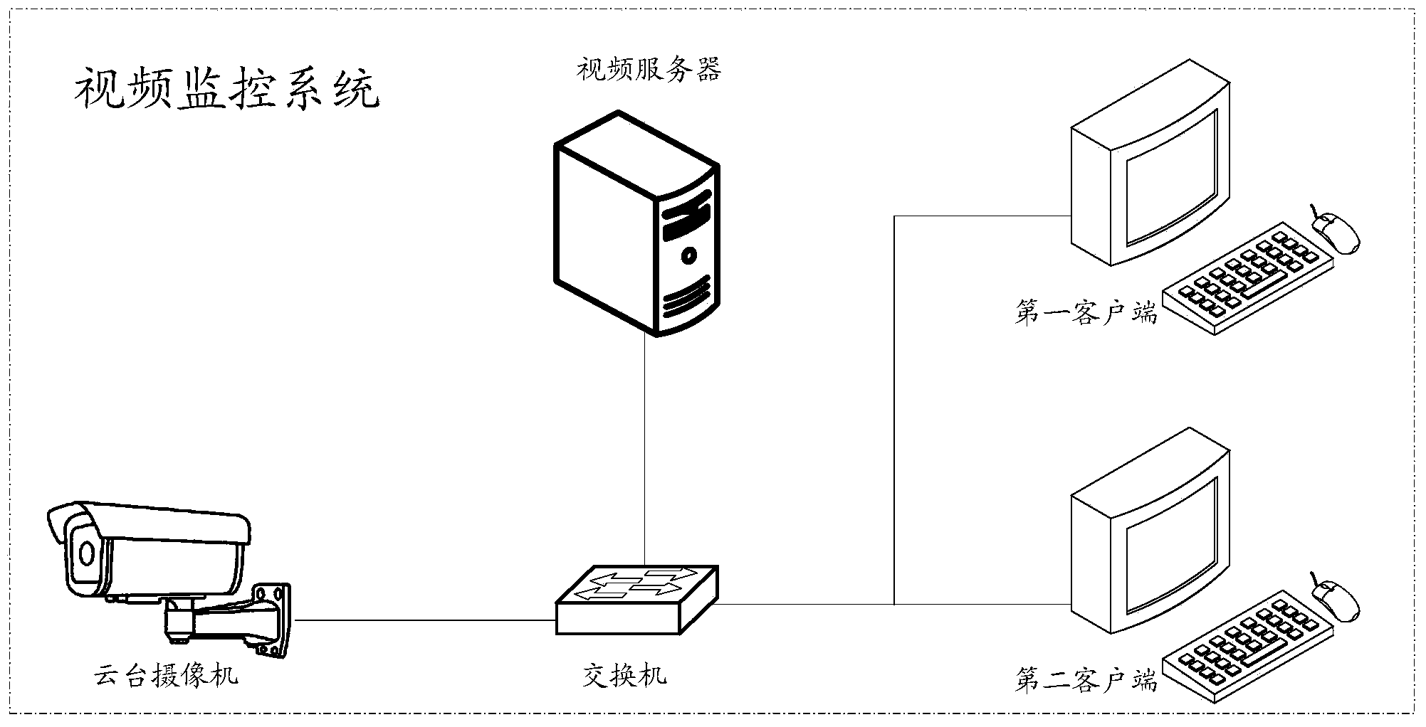
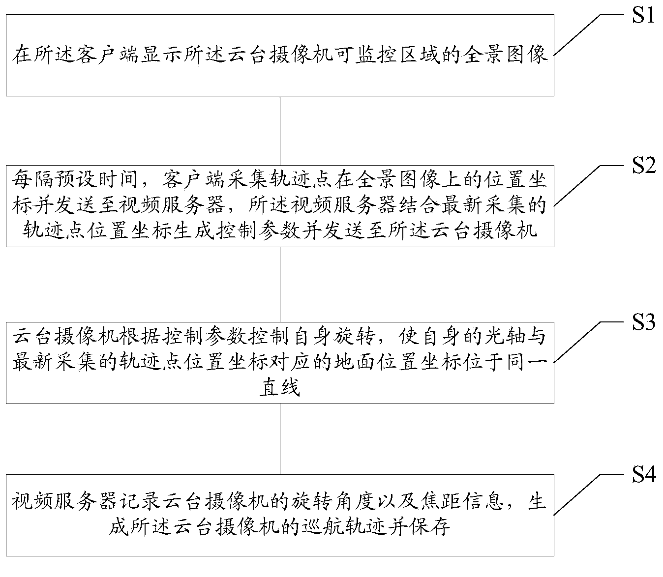
The invention provides a cruise control method for a tripod head video camera. The method is applied to a video monitoring system which comprises the tripod head video camera, a video server and a client terminal. The method comprises the steps that (S1) a panoramic picture of a monitorable area of the tripod head video camera is displayed on the client terminal; (S2) the client terminal collects position coordinates of a tracing point on the panoramic picture and sends the position coordinates the video server every other preset time, and the video server generates control parameters by combining the position coordinates of the tracing point collected latest and sends the control parameters to the tripod head video camera; (S3) the tripod head video camera controls own rotation according to the control parameters, and the own optical axis of the tripod head video camera is made to be located on a same straight line with a ground location coordinate corresponding to the position coordinates of the tracing point collected latest. According to the cruise control method for the tripod head video camera, the rotation of the tripod head video camera can be control by moving the tracing point, a user can acquire all the information around a monitoring point conveniently through the panoramic picture, observation and judgment over an overall situation by the user are facilitated, and therefore better monitoring effects can be achieved.

Description

technical field [0001] The invention relates to the technical field of video surveillance, in particular to a cruise control method for a pan-tilt camera. Background technique [0002] Video surveillance is an important part of the security system. With the rapid development of computer, network communication and image processing technologies, video surveillance technology has also made great progress. At present, video surveillance technology has been widely used in various fields, especially in some fields such as public safety and emergency command. [0003] In the current video surveillance system, in order to reduce the deployment density of cameras, PTZ cameras are deployed at many monitoring points. Using the rotation and zoom functions of the PTZ camera, one PTZ camera can monitor a large area in real time. Whether the operation of the PTZ camera is fast or not has become an important indicator in the monitoring system, which affects the user's use effect to a larg...

Claims


Application Information

Patent Timeline
IPC IPC(8): H04N7/18H04N5/232
Inventor 苏志杰
Owner ZHEJIANG UNIVIEW TECH CO LTD
Learn More