Refrigerator

A cold storage and refrigerant technology, applied in the field of cold storage, can solve problems such as increased power consumption, increased assembly and installation man-hours, and blockage of the suction port 118

Inactive Publication Date: 2014-05-28
PANASONIC CORP
View PDF8 Cites 8 Cited by
  • Summary
  • Abstract
  • Description
  • Claims
  • Application Information

AI Technical Summary

Problems solved by technology

Therefore, there is a problem in that the cost of materials, the man-hours for assembling the unit, and the man-hours for installing the refrigerator main body increase, and as a result, it becomes a product that is not easy for users to buy.
Therefore, there is a problem that dust adheres to the vicinity of the air inlet 118 on the leeward side of the condenser 113, and the air inlet 118 is clogged for a short time.
If the intake port 118 on the leeward side of the condenser 113 is blocked, the air flowing in from the upwind side exchanges heat with the condenser 113 and the temperature rises, so the condensation temperature of the condenser 113 rises, which causes an increase in power consumption.

Method used


Image

  • Refrigerator
  • Refrigerator
  • Refrigerator

Examples


no. 1 Embodiment approach )

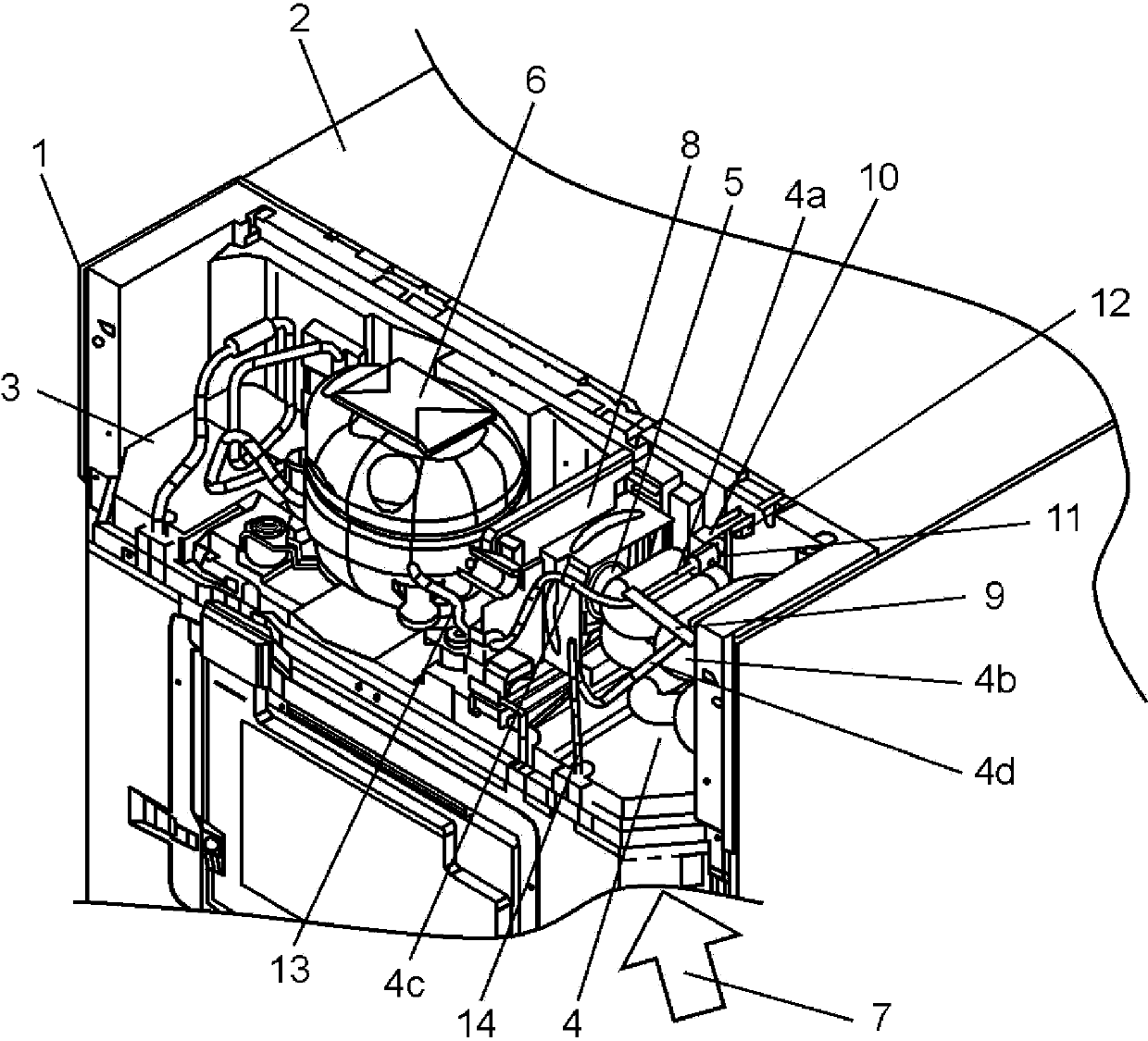
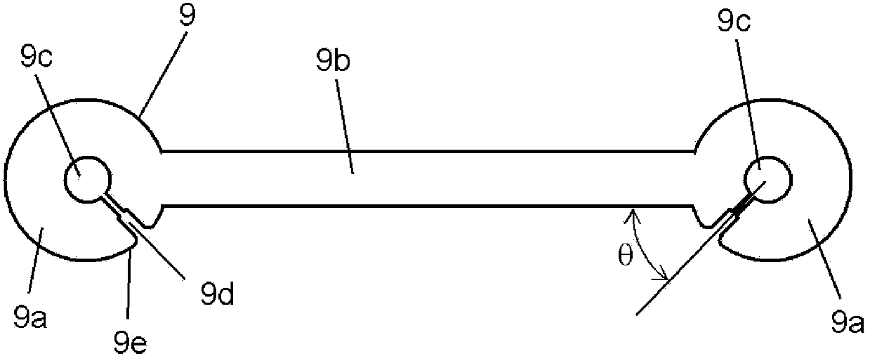
[0056] figure 1 It is the rear perspective view of the refrigerator of 1st Embodiment of this invention, figure 2 It is a plan view of the connection member of the refrigerator of 1st Embodiment of this invention.

[0057] exist figure 1 Among them, the refrigerator 1 has: a housing 2 , an upper mechanical chamber 3 arranged on the upper part of the housing 2 , a condenser 4 , a fan 5 and a compressor 6 . In the upper machine room 3, a condenser 4, a fan 5, and a compressor 6 are sequentially arranged from the windward side, and the air 7 on the upper part of the refrigerator 1 is sucked by driving the fan 5, and the condenser 4 and the compressor 6 are air-cooled. In addition, the fan 5 is attached to a fixing member 8 that divides the air passage in the upper machine room 3 into a space on the windward side and a space on the leeward side of the fan 5 .

[0058] Here, the condenser 4 is constituted by a spiral finned tube in which a strip-shaped fin 4b is wound around ...

no. 2 Embodiment approach )

[0082] Figure 4 It is a rear exploded perspective view of the refrigerator of 2nd Embodiment of this invention.

[0083] In addition, the description of the part to which the same structure and the same technical idea as 1st Embodiment can be applied is abbreviate|omitted. In addition, the present embodiment can be implemented in combination with the structure of the first embodiment, and it can be applied in combination as long as there is no problem.

[0084] exist Figure 4 Among them, the refrigerator 21 includes: a casing 22 of the refrigerator 21 ; In the lower machine room 23, a condenser 4, a fan 5, and a compressor 6 are arranged sequentially from the windward side, and the fan 5 is driven to suck air 7 from the upper part of the refrigerator, thereby air-cooling the condenser 4 and the compressor 6.

[0085] Moreover, the fan 5 is attached to the fixing member 8, and the fixing member 8 divides the air passage area in the lower machine room 23 into the upwind sid...

no. 3 Embodiment approach )

[0094] Figure 5 It is an exploded perspective view of the refrigerator of the third embodiment of the present invention, Figure 6 It is the detailed figure of the condenser of the refrigerator which concerns on 3rd Embodiment of this invention, Figure 7 yes Figure 6 Sectional view shown in 6-6.

[0095] exist Figure 5 to Figure 7Among them, the refrigerator 51 includes: a housing 52 , and a lower mechanical chamber 53 , a condenser 54 , a fan 55 , and a compressor 56 arranged at the lower part of the housing 52 . In the lower machine room 53 , a condenser 54 , a fan 55 , and a compressor 56 are installed in this order from the windward side. The condenser 54 and the compressor 56 are air-cooled by driving the fan 55 to suck the air 57 in the upper part of the refrigerator. Moreover, the fan 55 is attached to the fixing member 58, and the fixing member 58 divides the air passage area in the lower machine room 53 into the upwind side space 53a of the fan 55, and the le...


PUM


Abstract

A refrigerant pipe (4a) of a condenser (4) is helically wound into an oval shape, and the center of the helical winding forms a shape that meanders in the vertical direction with respect to the main shaft of a blower (5). The inlet (4c) and the outlet (4d) of the refrigerant are connected by a rubber connection member (9). The connection member (9) serves as a rubber vibration damper that absorbs the vibration of the condenser (4). In addition to suppressing vibration, the connection member (9) also serves to relatively position the inlet (4c) and the outlet (4d). Thus, there is no need for a positioning component, and the number of components is reduced.

Description

technical field [0001] The present invention relates to a refrigerator in which a condenser and a compressor are air-cooled (air-cooled) by a fan, and an inexpensive fixing member capable of easily suppressing noise and vibration of the condenser is installed. [0002] In addition, the present invention relates to a refrigerator in which a condenser and a compressor are air-cooled by a fan, and a condenser that can be housed in a narrow space and efficiently dissipates heat is mounted. Background technique [0003] From the viewpoint of energy saving, in a household refrigerator, in addition to a condenser that is naturally air-cooled from the outer contour of the casing pasted inside the outer contour of the casing, a condenser that is air-cooled by a fan is also used in combination. However, in the home refrigerator, the size of the condenser main body and the air passage are restricted from the viewpoint of saving space. Therefore, a method of fixing the refrigerator bod...

Claims


Application Information

Patent Timeline
Patent Type & Authority Applications(China)
IPC IPC(8): F25D19/00
CPCF28D1/0477F25B2500/13F25D23/006F28D2021/007F28F2265/30F28F1/36
Inventor 宫坂亚有子西村智之国分尚武中村光男境寿和
Owner PANASONIC CORP
Why Eureka
Try Eureka