Solar cell and method for manufacturing the same

A solar cell and back electrode layer technology, which is applied in the direction of final product manufacturing, sustainable manufacturing/processing, circuits, etc., can solve the problems of reducing solar cell efficiency and increasing contact resistance, so as to increase electron collection efficiency and reduce Effects of improving contact resistance and current characteristics

Inactive Publication Date: 2014-05-28
LG INNOTEK CO LTD
View PDF6 Cites 2 Cited by
  • Summary
  • Abstract
  • Description
  • Claims
  • Application Information

AI Technical Summary

Problems solved by technology

[0004] However, when the back electrode layer is connected to the transparent electrode layer, the contact resistance between the back electrode layer and the transparent electrode layer increases, thereby reducing the efficiency of the solar cell

Method used


Image

  • Solar cell and method for manufacturing the same
  • Solar cell and method for manufacturing the same
  • Solar cell and method for manufacturing the same

Examples


Embodiment Construction

[0017] Embodiments will be described in more detail below with reference to the accompanying drawings.

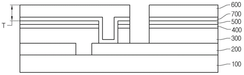
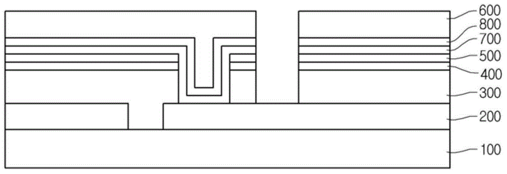
[0018] figure 1 is a sectional view showing a solar cell according to an embodiment, and figure 2 is a cross-sectional view showing a modified example of the solar cell according to the embodiment.

[0019] see figure 1 , The solar cell according to the embodiment includes a substrate 100, a back electrode layer 200 on the substrate 100, a light absorbing layer 300 on the back electrode layer 200, a first buffer layer 400 and a second buffer layer on the light absorbing layer 300 500 , the transparent electrode layer 600 on the second buffer layer 500 and the impurity doped layer 700 between the light absorbing layer 300 and the transparent electrode layer 600 .

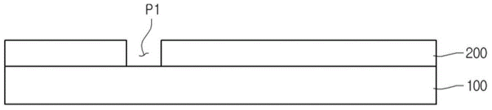
[0020] The substrate 100 may have a flat plate shape and include a transparent glass material.

[0021] Substrate 100 may be rigid or flexible. Besides a glass substrate, a plastic substrate or a metal subst...


PUM


Abstract

A solar cell includes a substrate; a back electrode layer on the substrate; a light absorbing layer on the back electrode layer; and an impurity doping layer between the light absorbing layer and the transparent electrode layer. In the solar cell, contact resistance during contact of the transparent electrode layer with the back electrode layer is reduced by making an impurity doping amount of the impurity doping layer greater than that of the transparent electrode layer.

Description

technical field [0001] Embodiments relate to a solar cell and a method of manufacturing the same. More particularly, embodiments relate to a solar cell with improved efficiency and a method of manufacturing the same. Background technique [0002] Generally, solar cells convert solar energy into electrical energy. Recently, with the increase in energy consumption, solar cells have been widely used commercially. [0003] A solar cell may be formed by laminating a back electrode layer, a light absorbing layer, and a transparent electrode layer on a transparent glass substrate so that the back electrode layer can be electrically connected to the transparent electrode layer. [0004] However, when the back electrode layer is connected to the transparent electrode layer, the contact resistance between the back electrode layer and the transparent electrode layer increases, thereby reducing the efficiency of the solar cell. Contents of the invention [0005] technical problem ...

Claims


Application Information

Patent Timeline
Patent Type & Authority Applications(China)
IPC IPC(8): H01L31/048H01L31/18
CPCH01L31/0749Y02E10/541H01L31/068H01L27/1423H01L31/065H01L31/1884H01L27/1426H01L31/0322H01L31/046H01L31/0465Y02E10/547Y02P70/50H01L31/0445H01L31/0224H01L31/18
Inventor 沈洺奭
Owner LG INNOTEK CO LTD
Why Eureka
Try Eureka