Main motors for railway vehicles

A technology for main motors and railway vehicles, applied in AC motor control, electric motors, electric vehicles, etc., can solve problems such as main motor loss, achieve the effects of reducing low-order harmonic components, suppressing circulating current, and suppressing switching losses

Active Publication Date: 2016-07-13
MITSUBISHI ELECTRIC CORP
View PDF11 Cites 0 Cited by
  • Summary
  • Abstract
  • Description
  • Claims
  • Application Information

AI Technical Summary

Problems solved by technology

Moreover, the circuit configuration of the stator winding is usually related to the losses of the main motor

Method used


Image

  • Main motors for railway vehicles
  • Main motors for railway vehicles
  • Main motors for railway vehicles

Examples


Embodiment approach

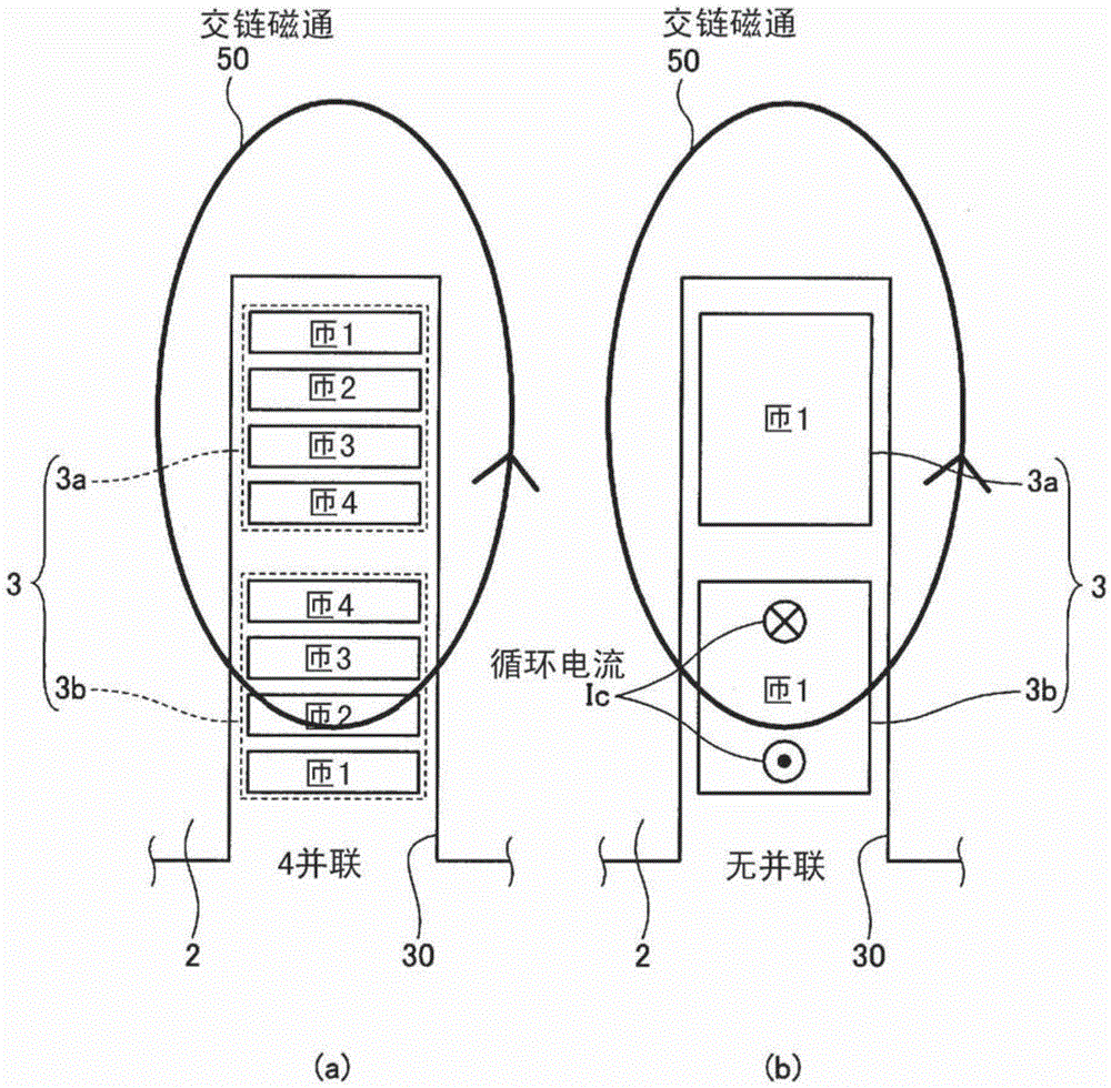
[0030] The main electric motor for railway vehicles (hereinafter simply referred to as "main electric motor") according to the present invention is an electric motor mounted on an electric train for driving a vehicle. The main motor is a three-phase AC motor, such as an induction motor. However, as long as the main motor has the same structure as the stator described below, it may be other than the induction motor, for example, may be a synchronous motor.

[0031] In electric vehicles, the inverter circuit usually converts the electric power collected by the overhead line into three-phase alternating current, and supplies the alternating current to the main motor. Here, when the trolley line is a DC trolley line, the DC power supplied from the trolley line is converted into AC power with variable voltage and variable frequency by an inverter circuit, and the AC power is supplied to the main motor. When the overhead line is an AC overhead line, the rectifier circuit is used to...


PUM


Abstract

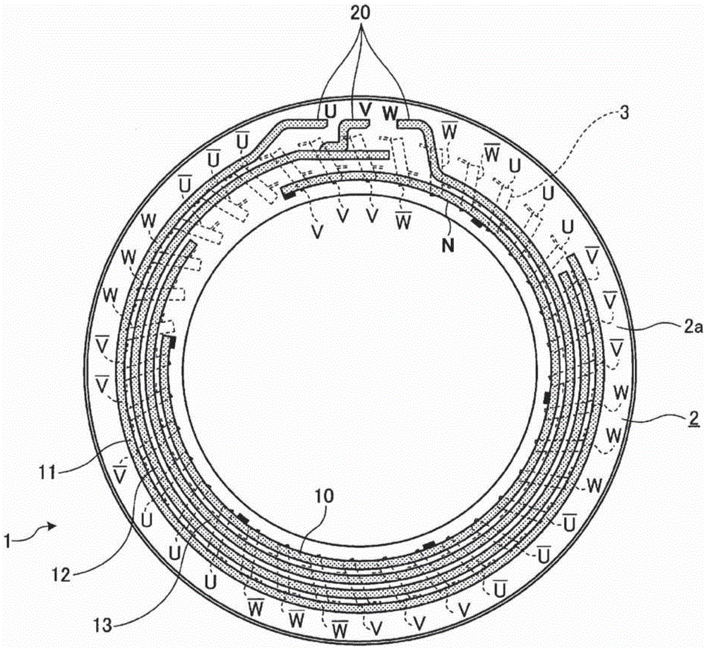
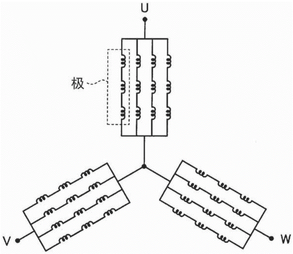
The main motor for a railway vehicle is rotationally driven upon receiving an AC power supplied from an inverter circuit that includes a switching element formed by using a wide bandgap semiconductor. The inverter circuit applies a voltage having a PWM waveform to the main motor for a railway vehicle in at least part of a speed range of an electric vehicle. The stator of the main motor for a railway vehicle is configured to include an annular stator core provided with a plurality of slots in a circumferential direction and coils that are wound on the stator core and are accommodated in the slots, and includes a stator winding that is three-phase star-connected and is composed of parallel circuits the number of which is the same as the number of poles for each phase.

Description

technical field [0001] The present invention relates to a main electric motor for a railway vehicle. Background technique [0002] In general, electric cars obtain propulsion by converting electric power collected from overhead lines into three-phase alternating current by using an inverter circuit, and supplying the alternating current to a main motor for driving. For example, in the case of a DC overhead line, an inverter circuit is usually used to convert the DC power supplied by the overhead line into AC power with variable voltage and frequency, and use this AC power to drive the main motor. In the case of AC overhead lines, the following structure is generally adopted: that is, the AC power supplied by the overhead line is temporarily converted into DC power by a rectifier circuit, and then the DC power is converted into a variable-voltage, frequency-variable power by an inverter circuit. Transformed alternating current, and use this alternating current to drive the m...

Claims


Application Information

Patent Timeline
Patent Type & Authority Patents(China)
IPC IPC(8): H02K3/04H02K3/50
CPCH02K3/12H02K3/28H02P25/22Y02T10/64H02K3/38H02K2203/09
Inventor 金子健太米谷晴之
Owner MITSUBISHI ELECTRIC CORP
Why Eureka
Try Eureka