Power supply device

a power supply device and power supply technology, applied in the direction of electric variable regulation, process and machine control, instruments, etc., can solve problems such as switching loss, and achieve the effect of suppressing switching loss

Inactive Publication Date: 2021-08-26
YAZAKI CORP
View PDF0 Cites 0 Cited by
  • Summary
  • Abstract
  • Description
  • Claims
  • Application Information

AI Technical Summary

Benefits of technology

[0005]The present invention is designed in view of the aforementioned circumstances, and an object thereof is to provide a power supply device capable of suppressing switching loss.

Problems solved by technology

By the way, with the DC / DC converter disclosed in Japanese Patent Application Laid-open No. 2016-135003, when the power supplied to the load part from the direct current power supply is small, for example, sufficient energy is not accumulated in the resonant reactor so that zero voltage switching cannot be performed, which may cause switching loss.

Method used


Image

  • Power supply device
  • Power supply device
  • Power supply device

Examples


embodiments

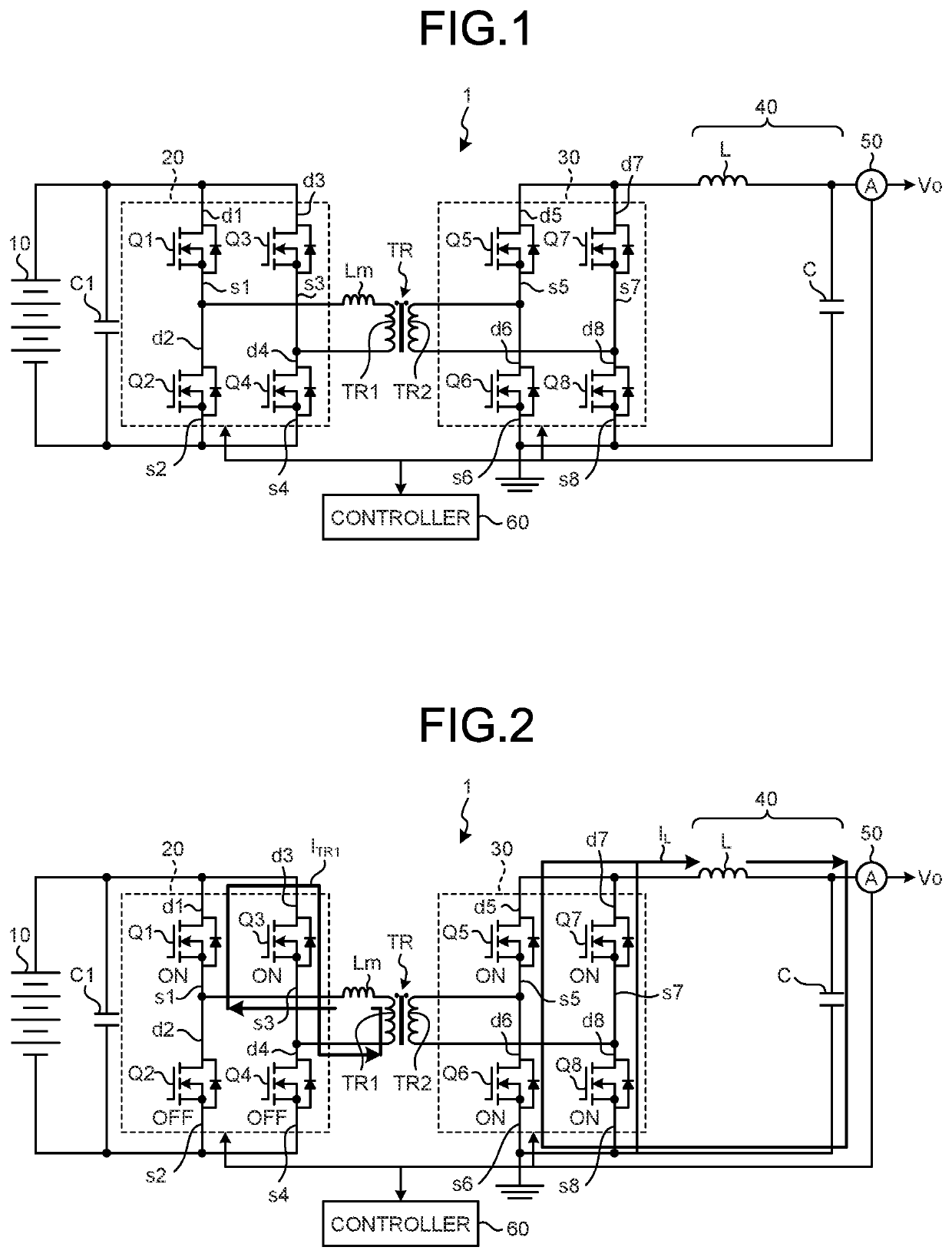
[0033]A power supply device 1 according to a first embodiment of the present invention will be described with reference to the accompanying drawings. FIG. 1 is a circuit diagram illustrating a configuration example of the power supply device 1 according to the first embodiment. The power supply device 1 is a DC / DC converter that transforms a voltage of a power supplied from a direct current power supply 10 and supplies the power of an output voltage Vo to a load part (not illustrated). The power supply device 1 is a phase-shift full-bridge type insulating DC / DC converter, for example. The power supply device 1 includes the direct current power supply 10, a switching circuit 20, a transformer TR, a rectifier circuit 30, a smoothing circuit 40, a current detection unit 50, and a controller 60 as illustrated in FIG. 1.

[0034]The direct current power supply 10 supplies the direct current power. The direct current power supply 10 is configured by including a plurality of battery cells. Th...

second embodiment

[0062]Next, a power supply device 1A according to a second embodiment will be described. In the second embodiment, same reference signs are applied to structural elements same as those of the first embodiment, and detailed explanations thereof are omitted. The power supply device 1A according to the second embodiment is different from the power supply device 1 according to the first embodiment in respect that it includes a rectifier circuit 30A utilizing a center tap CT of the transformer TR.

[0063]As illustrated in FIG. 12, the transformer TR has the center tap CT provided in the center of the secondary winding TR2. The center tap CT is connected to the coil L of the smoothing circuit 40.

[0064]The rectifier circuit 30A is configured by including a FET Q9 and a FET Q10, and performs full-wave rectification by those switching elements. The FET Q9 and the FET Q10 are N-channel type MOSFETs, for example.

[0065]In the rectifier circuit 30A, a drain terminal 9d of the FET Q9 is connected t...


PUM


Abstract

In a power supply device, a primary winding is connected to, out of drain-source terminals of FETs as the subject of soft switching control, a source terminal and a drain terminal where the potential of the drain-source terminals is adjusted. In a case where a current value detected by a current detection unit is equal to or smaller than a reference current value defined in advance, a controller allows the current flowing backward due to resonance of a coil and a capacitor of a smoothing circuit to flow in a secondary winding via a rectifier circuit.

Description

CROSS-REFERENCE TO RELATED APPLICATION(S)[0001]The present application claims priority to and incorporates by reference the entire contents of Japanese Patent Application No. 2020-026959 filed in Japan on Feb. 20, 2020.BACKGROUND OF THE INVENTION1. Field of the Invention[0002]The present invention relates to a power supply device.2. Description of the Related Art[0003]Conventionally, as a power supply device, for example, Japanese Patent Application Laid-open No. 2016-135003 discloses a DC / DC converter that transforms a voltage of a power supplied from a direct current power supply and supplies the power to a load part. The DC / DC converter includes: an inverter circuit that is controlled by soft switching and converts a direct current power supplied from a direct current power supply to an alternating current power; a transformer that transforms the alternating current power converted by the inverter circuit; a rectifier circuit that rectifies the alternating current power transform...

Claims


Application Information

Patent Timeline
Patent Type & Authority Applications(United States)
IPC IPC(8): H02M3/335H02M1/08H02M1/34H02M3/337
CPCH02M3/33569H02M1/08H02M2001/0058H02M3/337H02M1/34H02M3/33592H02M3/33584H02M1/0009H02M1/0032H02M1/0058H02M3/33573Y02B70/10
Inventor KANDA, KEISUKEITO, SATOSHIYOSHIMITSU, SHOTA
Owner YAZAKI CORP
Why Eureka
Try Eureka