Semiconductor device
a technology of semiconductor switching elements and capacitors, applied in the direction electrical equipment, basic electric elements, etc., can solve the problems of mainly caused power loss of semiconductor switching elements, method of reducing cgc while suppressing adverse effects on other characteristics, and method of reducing cgc has not been sufficiently studied so far, so as to achieve the effect of suppressing switching loss
- Summary
- Abstract
- Description
- Claims
- Application Information
AI Technical Summary
Benefits of technology
Problems solved by technology
Method used
Image
Examples
first preferred embodiment
[0036](Configuration)
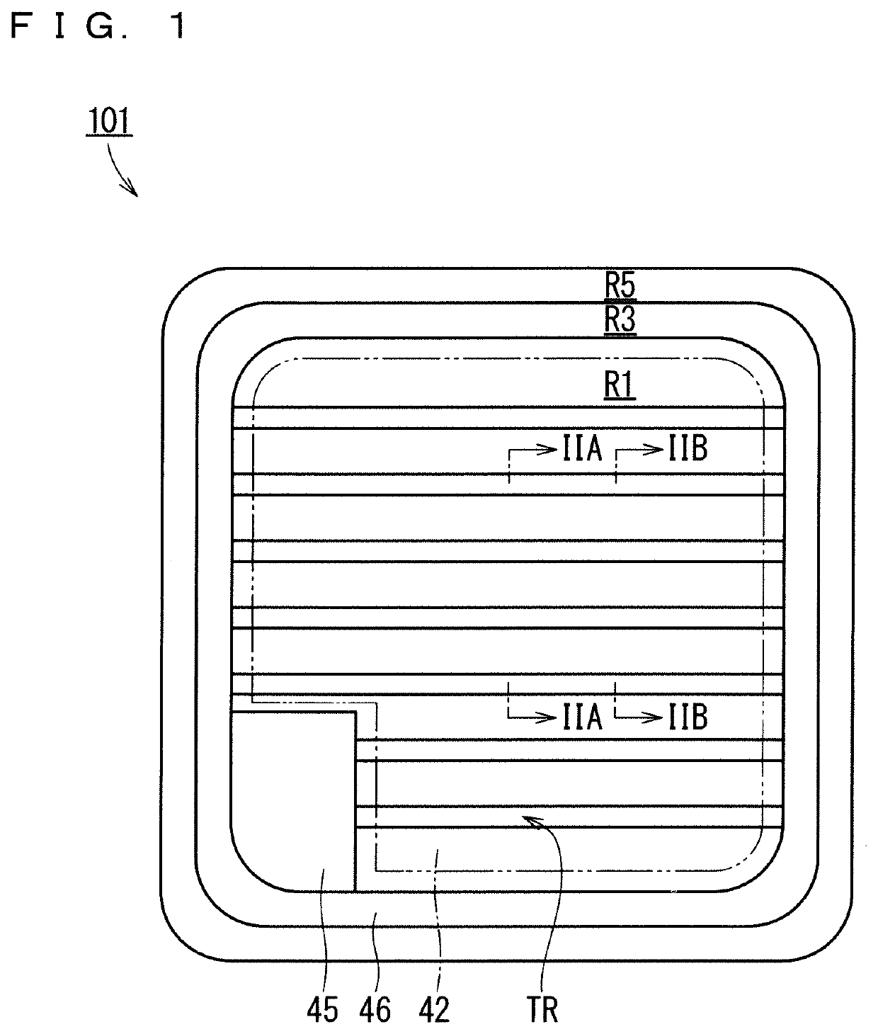
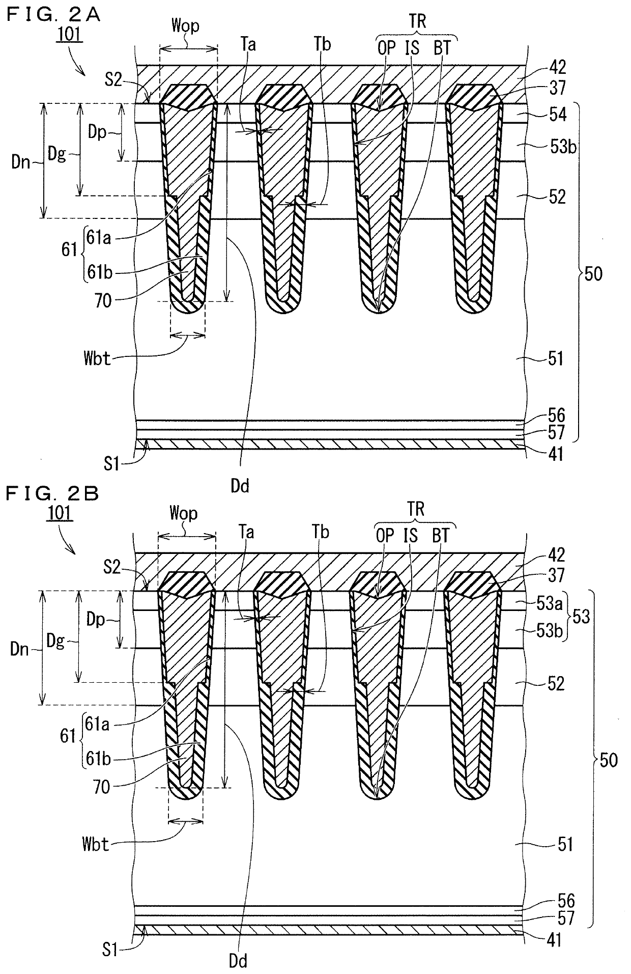
[0037]FIG. 1 is a top view schematically showing a configuration of an IGBT 101 (semiconductor device) in a first preferred embodiment. FIGS. 2A and 2B are partial cross-sectional views adjacent to each other in a cell region R1 (FIG. 1) of the IGBT 101, and specifically are partial cross-sectional views along line IIA-IIA and line IIB-IIB in FIG. 1. Meanwhile, in FIG. 1, an outer edge of an emitter electrode 42 (second main electrode) is exclusively shown by a two-dot chain line in order to make the drawing easily viewable.
[0038]The IGBT 101 has a semiconductor substrate 50, an internal insulating film 61, a trench electrode 70, a collector electrode 41 (first main electrode), the emitter electrode 42, and an interlayer insulating film 37. The semiconductor substrate 50 has a surface S1 (first surface) and a surface S2 (second surface) that is a surface opposite to the surface S1. In this specification, a “depth” in the semiconductor substrate 50 is defined as ...
second preferred embodiment
[0054](Configuration)
[0055]FIG. 11 is a partial cross-sectional view schematically showing a configuration of an IGBT 102 (semiconductor device) in a second preferred embodiment. Also in the IGBT 102, as in the IGBT 101 (FIGS. 2A and 2B: the first preferred embodiment), an internal insulating film 61 has a thickness Ta at a portion facing a p base layer 53, has a thickness Tb at a portion facing an n− drift layer 51, and has the thickness Ta and the thickness Tb at a portion facing an n carrier storage layer 52, and the thickness Tb is thicker than the thickness Ta. Further, in the present preferred embodiment, a portion of the internal insulating film 61 deeper than the deepest part of a trench electrode 70 has a thickness Tc (third thickness) thicker than the thickness Tb. Specifically, a lower portion 61b of the internal insulating film 61 has the thickness Tc thicker than the thickness Tb on a bottom part BT of a trench TR.
[0056]Note that, in this specification, the “thickness” ...
third preferred embodiment
[0060](Configuration)
[0061]FIG. 12 is a partial cross-sectional view schematically showing a configuration of an IGBT 201 (semiconductor device) in a third preferred embodiment. The IGBT 201 has a trench electrode 71 instead of the trench electrode 70 (FIG. 1: the first preferred embodiment). The trench electrode 71 has an upper electrode 71a and a buried electrode 71b. The upper electrode 71a is in contact with a portion of an internal insulating film 61 having a thickness Ta. The buried electrode 71b is in contact with a portion of the internal insulating film 61 having a thickness Tb. Specifically, the trench electrode 71 has the upper electrode 71a disposed shallower than a depth Dg, and the buried electrode 71b disposed deeper than the upper electrode 71a. The IGBT 201 has an isolation insulating film 63 that separates the upper electrode 71a and the buried electrode 71b in a trench TR. In the present preferred embodiment, the buried electrode 71b is electrically connected to t...
PUM
| Property | Measurement | Unit |
|---|---|---|
| conductivity | aaaaa | aaaaa |
| concentration | aaaaa | aaaaa |
| conductivity type | aaaaa | aaaaa |
Abstract
Description
Claims
Application Information
 - R&D
- Intellectual Property
- Life Sciences
- Materials
- Tech Scout
- Unparalleled Data Quality
- Higher Quality Content
- 60% Fewer Hallucinations
Browse by: Latest US Patents, China's latest patents, Technical Efficacy Thesaurus, Application Domain, Technology Topic, Popular Technical Reports.
© 2025 PatSnap. All rights reserved.Legal|Privacy policy|Modern Slavery Act Transparency Statement|Sitemap|About US| Contact US: help@patsnap.com


