Power supply device

a power supply device and power supply technology, applied in the direction of electric variable regulation, process and machine control, instruments, etc., can solve problems such as switching loss, and achieve the effect of suppressing switching loss and lowering potential

Active Publication Date: 2020-12-10
YAZAKI CORP
View PDF0 Cites 0 Cited by
  • Summary
  • Abstract
  • Description
  • Claims
  • Application Information

AI Technical Summary

Benefits of technology

[0006]In order to achieve the above mentioned object, a power supply device according to one aspect of the present invention includes a power conversion inductor that outputs power input from a first end to a second end; a first output terminal that is connected to the second end of the power conversion inductor and outputs power; a second output terminal that is a terminal different from the first output terminal, is connected to the second end of the power conversion inductor, and outputs power; a first switching element that is provided between the second end of the power conversion inductor and the first output terminal and adjusts a current output from the power conversion inductor to the first output terminal; a second switching element that is provided between the second end of the power conversion inductor and the second output terminal and adjusts a current output from the power conversion inductor to the second output terminal; a soft switching circuit including a third switching element that is connected in parallel with the second switching element and conducts or cuts off a current, and a soft switching inductor provided between the third switching element and the second output terminal; and a controller configured to control the first switching element, the second switching element, and the soft switching circuit, wherein the controller lowers a potential from the first output terminal by turning on the third switching element and sets a potential difference between an input terminal and an output terminal of the second switching element to zero to suppress a switching loss when the second switching element is turned on.

Problems solved by technology

Meanwhile, in the above-described single-inductor multi-output circuit, for example, noise is generated due to a current flowing due to a reverse recovery characteristic of a parasitic diode of the switching element, and there is a possibility that this noise may cause a switching loss.

Method used


Image

  • Power supply device
  • Power supply device
  • Power supply device

Examples


embodiment

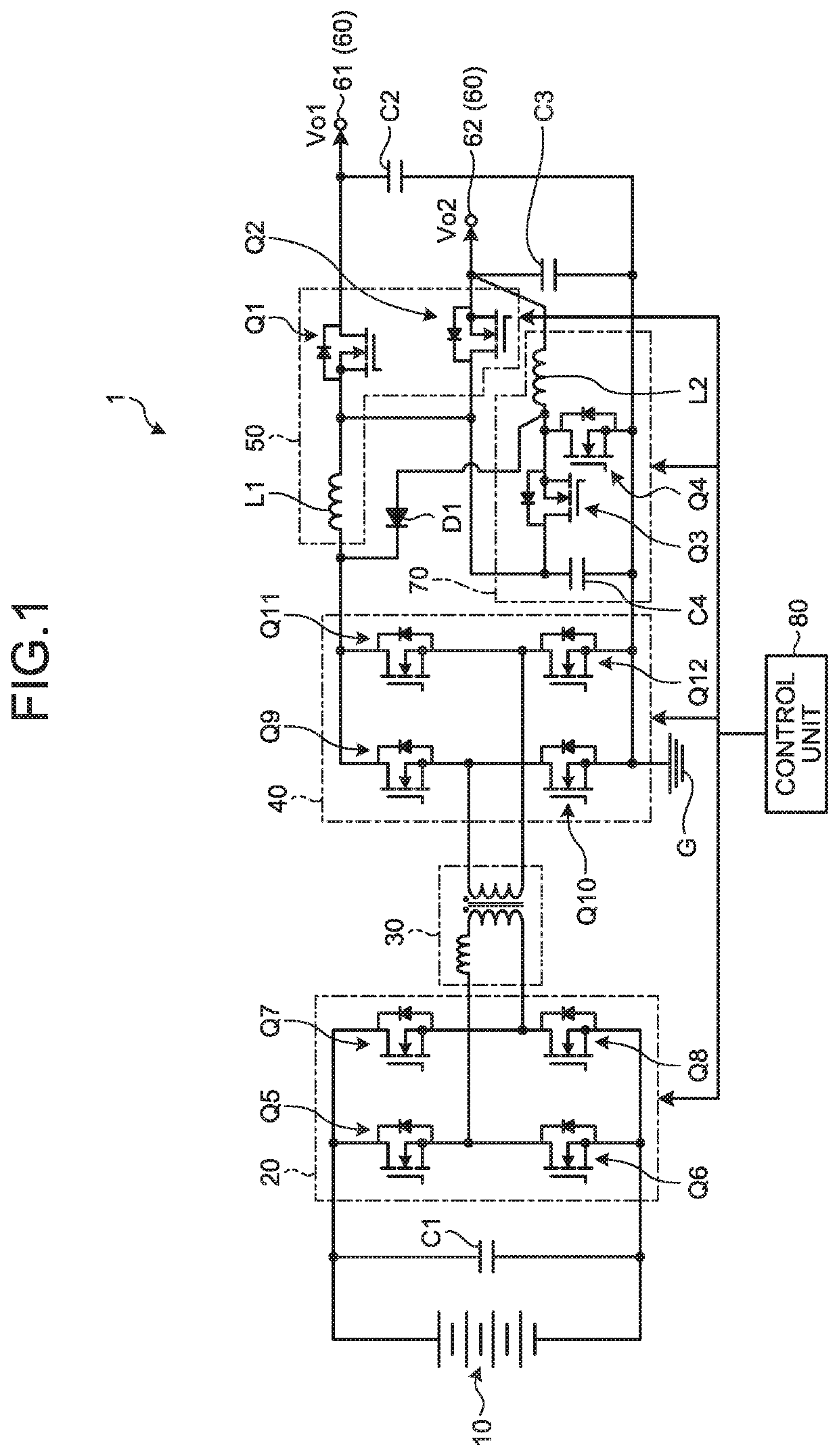
[0027]A multi-output power supply device (power supply device) 1 according to an embodiment will be described with reference to the drawings. FIG. 1 is a circuit diagram illustrating a configuration example of a multi-output power supply device 1 according to the embodiment. The multi-output power supply device 1 forms a plurality of different power supplies from a high-voltage power supply 10. The multi-output power supply device 1 is mounted on a vehicle, for example, and supplies power to each electric component of the vehicle. As illustrated in FIG. 1, the multi-output power supply device 1 includes a power supply 10, full-bridge circuit 20, a transformer 30, a rectifier circuit 40, a single inductor multiple output (SIMO) circuit 50, an output unit 60, a chopper circuit 70 serving as a soft switching circuit, a diode D1, and a controller 80.

[0028]The power supply 10 supplies DC power. The power supply 10 is configured, for example, by connecting a plurality of battery cells in ...


PUM


Abstract

A multi-output power supply device includes an inductor, a first output terminal, a second output terminal, an FET, an FET, a chopper circuit, and a controller. The FET adjusts a current output from the inductor to the first output terminal. The FET adjusts a current output from the inductor to the second output terminal. The chopper circuit has the FET and the inductor. The FET is connected in parallel with the FET, and conducts or cuts off a current. The inductor is provided between the FET and the second output terminal. For example, the controller lowers a potential from the first output terminal by turning on the FET and sets a potential difference between a drain terminal and a source terminal of the FET to zero to suppress a switching loss when the FET is turned on.

Description

CROSS-REFERENCE TO RELATED APPLICATION(S)[0001]The present application claims priority to and incorporates by reference the entire contents of Japanese Patent Application No. 2019-104241 filed in Japan on Jun. 4, 2019.BACKGROUND OF THE INVENTION1. Field of the Invention[0002]The present invention relates to a power supply device.2. Description of the Related Art[0003]Conventionally, as a power supply device, for example, there is a single-inductor multi-output circuit that includes a single inductor and a plurality of switching elements, converts power output from the single inductor into power of a plurality of different voltages by the plurality of switching elements, and outputs the converted power. Note that Japanese Patent Application Laid-open No. 2004-135442 discloses a switching power supply device that includes a coil having an intermediate tap and supplies power of a plurality of voltages.[0004]Meanwhile, in the above-described single-inductor multi-output circuit, for exa...

Claims


Application Information

Patent Timeline
Patent Type & Authority Applications(United States)
IPC IPC(8): H02M3/335H02M1/088
CPCH02M3/33576H02M1/088H02M3/3353H02M1/0058H02M3/33561H02M7/4826Y02B70/10H02M1/0051H02M1/008H02M1/007H02M7/4811G05F1/577H02M3/1584H02M1/009
Inventor KANDA, KEISUKEYOSHIMITSU, SHOTA
Owner YAZAKI CORP
Why Eureka
Try Eureka